Deposit detector and controller using the detector
a technology of detector and controller, applied in the field of objects, can solve the problems of inability to perform the same and uniform control, and ineffective wiping only with a wiper
- Summary
- Abstract
- Description
- Claims
- Application Information
AI Technical Summary
Benefits of technology
Problems solved by technology
Method used
Image
Examples
embodiment 1
(Embodiment 1)
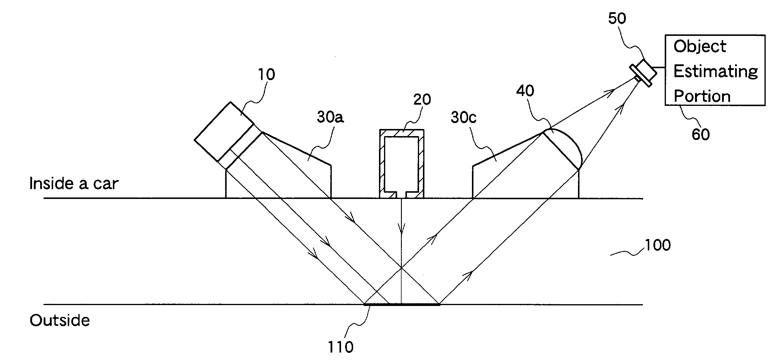
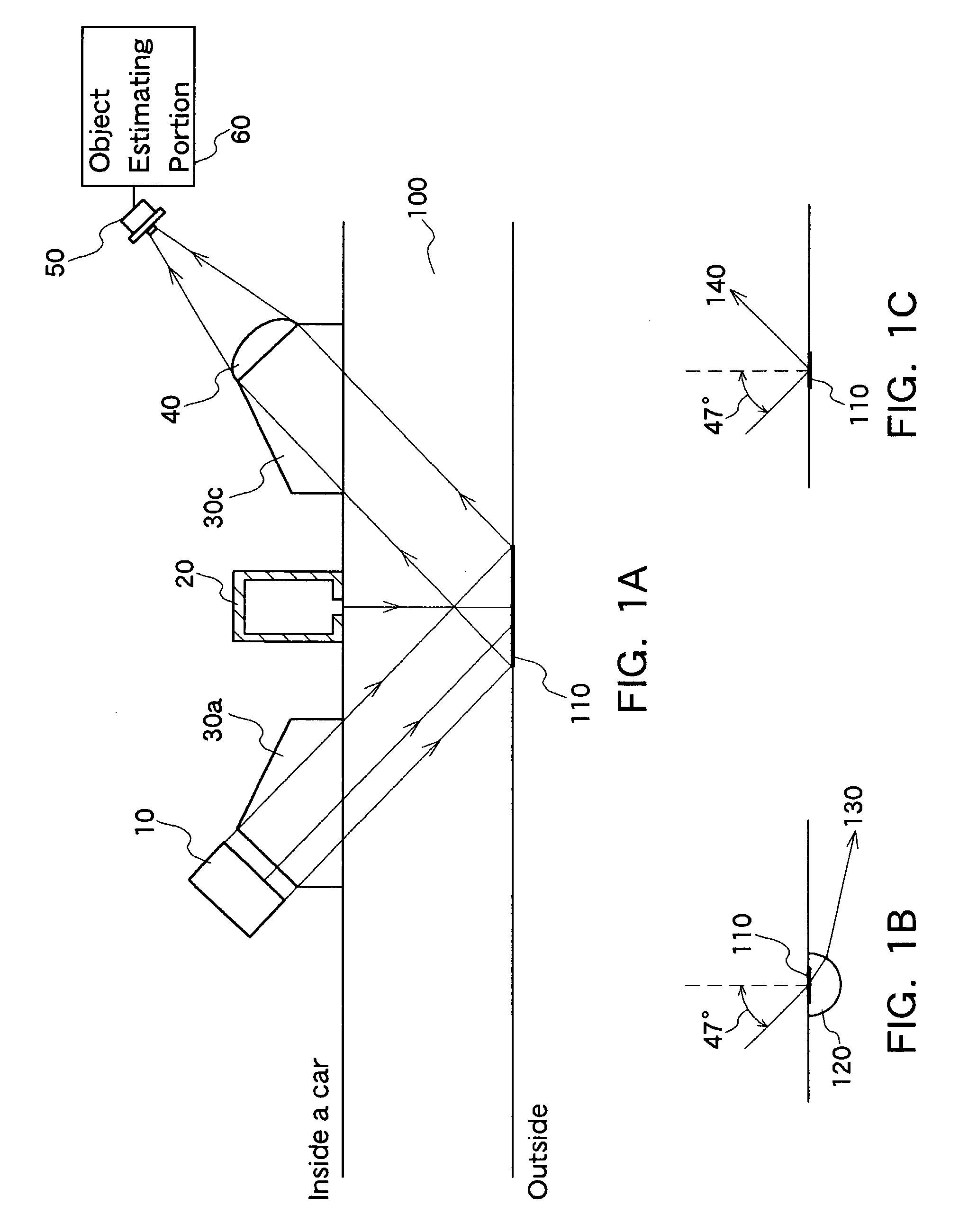
[0073]The first object-sensing device of the present invention will be described. An object-sensing device capable of estimating the presence of an object on a sensing surface and whether or not the object is a substance having light scattering properties will be described as Embodiment 1. In particular, taking as an example the case where the object is a rain drop and is muddy water, it is described that the former and the latter can be distinguished.
[0074]The basic principle of the object-sensing device of Embodiment 1 of the present invention is as follows. A reflected light from a light source for total reflection and scattering light from a light source for scattering light that are irradiated onto a sensing surface are received by a light receiver, and the levels of photo detection signals are analyzed so that a change in the total reflection condition and the scattering condition on the sensing surface due to the presence, the kind and the state of the object on...
embodiment 2
(Embodiment 2)
[0123]An object-sensing device of Embodiment 2 is an example in which an additional application function is provided for the process for estimating the kind and the state of an object in the object-sensing device of Embodiment 1 of the present invention. In particular, in this embodiment, it is estimated whether muddy water is in the state of so-called “muddy water” having a water content or in a dry state in distinction from each other when the object is muddy water, for example.
[0124]The device configuration and the arrangement of the components can be the same as in Embodiment 1, so that the description thereof is omitted. The process of the object-estimating portion 60 is different.
[0125]First, the principle of estimating whether muddy water is in the state of so-called “muddy water” having a water content or it is dry mud in distinction from each other will be described.
[0126]The so-called “muddy water” having a water content will not be described in detail, becau...
embodiment 3
(Embodiment 3)
[0141]An embodiment of a second object-sensing device of the present invention will be described.
[0142]The second object-sensing device of Embodiment 3 includes a light-receiving element array corresponding to the sensing surface, and light obtained via the sensing surface forms an image in the light-receiving element array by an imaging system lens and thus is received, and photo detection signals are formed into a signal pattern corresponding to an alignment of micro-light-receiving elements. The change portion of the signal pattern is analyzed, so that the presence of an object on the sensing surface, the kind thereof, or the like is detected. First, as Embodiment 3, an object-sensing device that can estimate the presence of an object on the sensing surface and whether or not the object is a substance having light scattering properties will be described. In particular, by taking as an example the case where the object is a rain drop and the case where the object is ...
PUM
 Abstract
Description
Claims
Application Information
 - R&D
- Intellectual Property
- Life Sciences
- Materials
- Tech Scout
- Unparalleled Data Quality
- Higher Quality Content
- 60% Fewer Hallucinations
Browse by: Latest US Patents, China's latest patents, Technical Efficacy Thesaurus, Application Domain, Technology Topic, Popular Technical Reports.
© 2025 PatSnap. All rights reserved.Legal|Privacy policy|Modern Slavery Act Transparency Statement|Sitemap|About US| Contact US: help@patsnap.com


