
Optical device for directing x-rays having a plurality of optical crystals

a technology of optical crystals and optical devices, applied in material analysis using wave/particle radiation, instruments, nuclear engineering, etc., can solve the problems of only having the option of producing high-intensity x-ray beams, anode x-ray tubes, synchrotrons,

Inactive Publication Date: 2006-04-25
X-RAY OPTICAL SYSTEM INC
View PDF10 Cites 103 Cited by
  • Summary
  • Abstract
  • Description
  • Claims
  • Application Information

AI Technical Summary

Problems solved by technology

In the past, expensive and powerful x-ray sources, such as rotating anode x-ray tubes or synchrotrons, were the only options available to produce high-intensity x-ray beams.
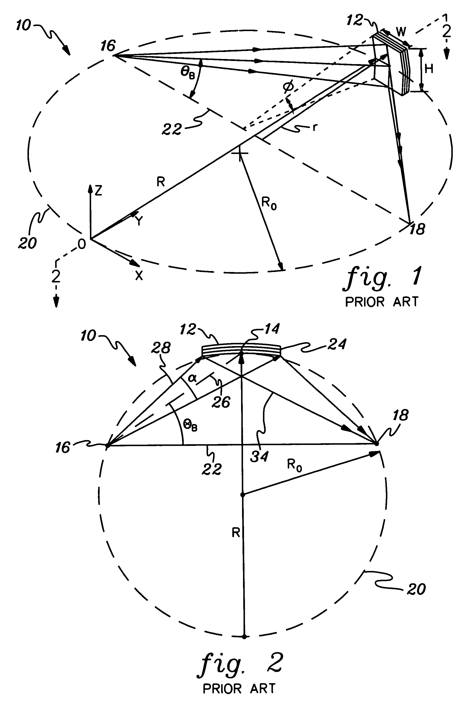
One limitation of crystals based on Johann geometry is a low radiation collection angle and, subsequently, reduced deflected beam flux and beam intensity.
However, the radiation collection angle having stepped geometry, as disclosed in U.S. Pat. No. 5,127,028, still has limitations.
For example, such stepped-geometry prior art crystals provide a limited x-ray collection angle are also difficult to manufacture.

Method used


Image

  • Optical device for directing x-rays having a plurality of optical crystals
  • Optical device for directing x-rays having a plurality of optical crystals
  • Optical device for directing x-rays having a plurality of optical crystals

Examples


examples

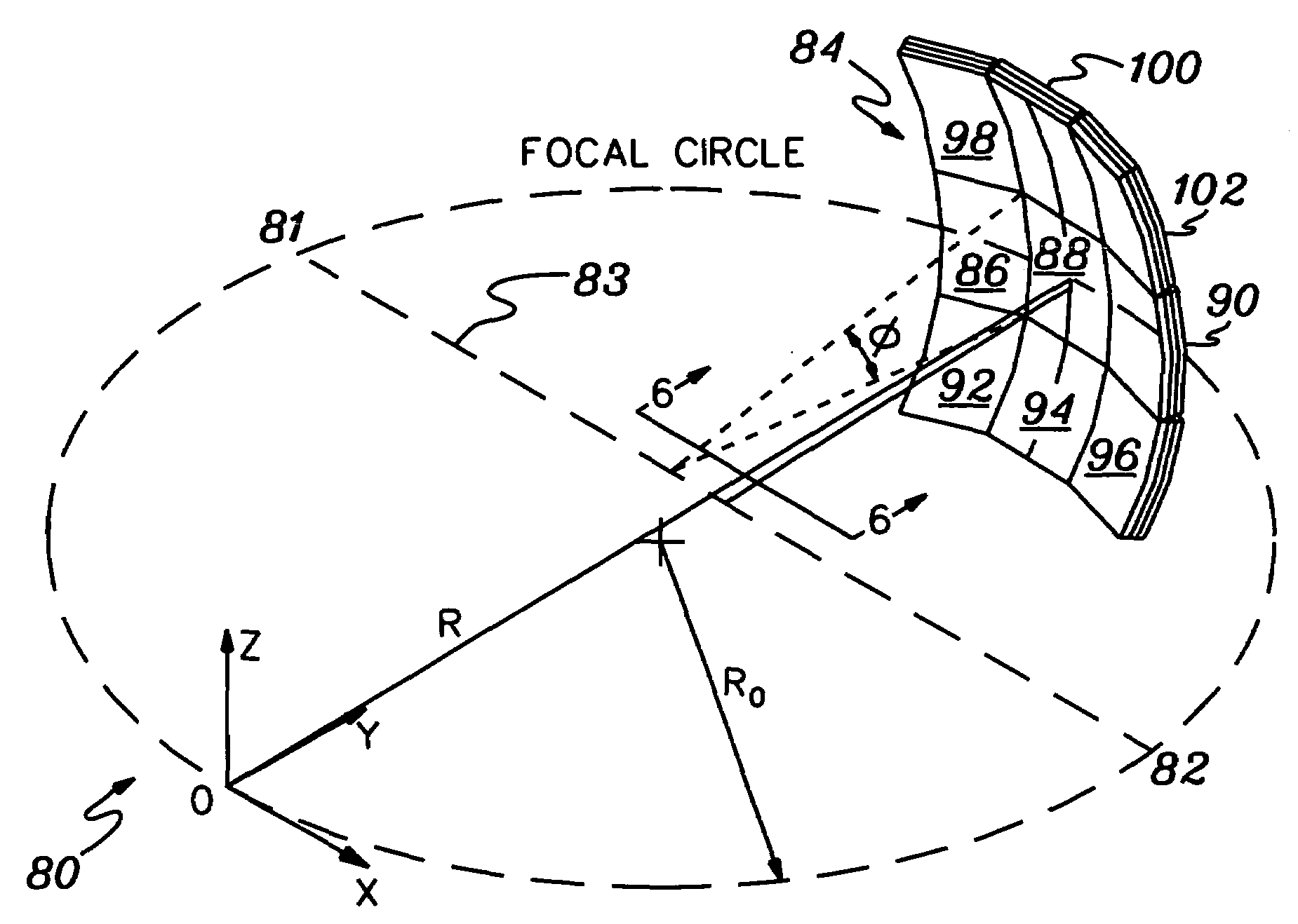
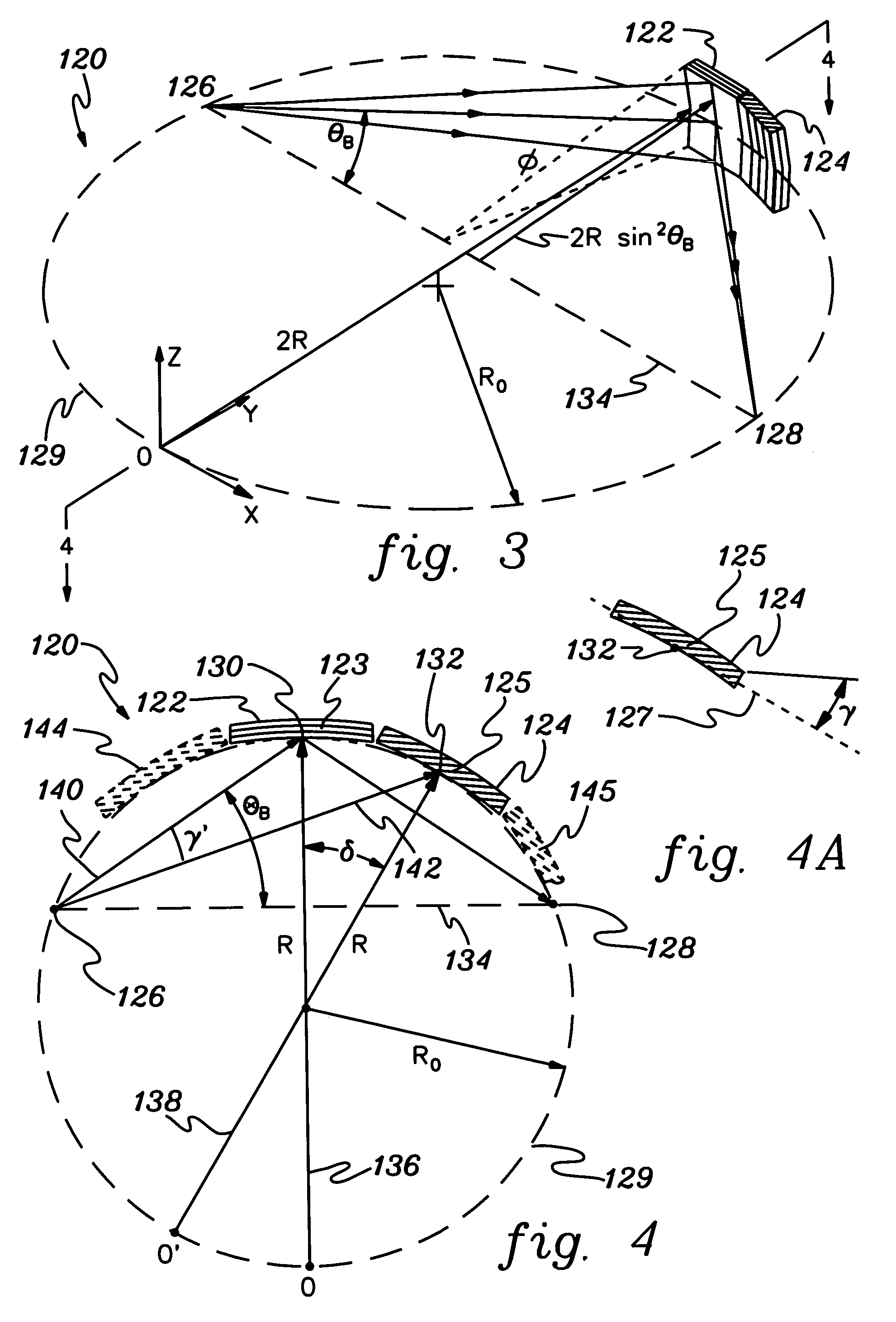
[0063]One or more aspects of the present invention are exemplified by the following examples. One specific example of an optic fabricated according to the aspect of the invention shown in FIGS. 3 and 4 is a Germanium (Ge) crystal optic for focusing Chromium (Cr) Kα radiation. The Ge crystal fabricated according to the present invention included reflection crystal planes Ge(111) and a Bragg angle for Cr Ka radiation of about 20.5°. According to one aspect of the invention, five Ge crystals pieces with inclined atomic diffraction planes of Ge(111) of −8 degrees, −4 degrees, η degrees, 4 degrees, and 8 degrees respectively were used. The Ge crystal device provided point focusing CrKα beam with a collection solid angle of 0.1 sr. for a 50° revolving angle, φ, see FIG. 1. This optic according to this aspect of the invention produced an x-ray image of about 3×10¹⁰ photons / sec at the target location using a 50 Watt, point x-ray source with Cr anode. This intense x-ray beam according to thi...


PUM

PropertyMeasurementUnit
toroidal angleaaaaaaaaaa

Abstract

Devices for improving the capturing and utilization of high-energy electromagnetic radiation, for example, x-rays, gamma rays, and neutrons, for use in physical, medical, and industrial analysis and control applications are disclosed. The devices include optics having a plurality of optical crystals, for example, doubly-curved silicon or germanium crystals, arranged to optimize the capture and redirection of divergent radiation via Bragg diffraction. In one aspect, a plurality of optic crystals having varying atomic diffraction plane orientations are used to capture and focus divergent x-rays upon a target. In another aspect, a two- or three-dimensional matrix of crystals is positioned relative to an x-ray source to capture and focus divergent x-rays in three dimensions.

Description

CROSS-REFERENCE TO RELATED APPLICATIONS[0001]This application is a continuation of PCT Application PCT / US2003 / 023412, filed Jul. 25, 2003, and published under the PCT Articles in English as WO 2004 / 013867 A2 on Feb. 12, 2004. PCT / US2003 / 023412 claimed priority to U.S. Provisional Application No. 60 / 400,809, filed Aug. 2, 2002. The entire disclosures of PCT / US2003 / 023412 and U.S. Ser. No. 60 / 400,809 are incorporated herein by reference in their entirety.STATEMENT REGARDING FEDERALLY SPONSORED RESEARCH OR DEVELOPMENT[0002]The U.S. Government has a paid-up license in this invention and the right in limited circumstances to require the patent owner to license others on reasonable terms as provided for by the terms of Contract #1 R43 RR14935-01 awarded by the National Institutes of Health.FIELD OF THE INVENTION[0003]This invention relates generally to devices and methods for diffracting or focusing high-energy electromagnetic radiation. Specifically, the present invention provides improv...

Claims


Application Information

Patent Timeline
Patent Type & Authority Patents(United States)
IPC IPC(8): G21K1/06G01N23/223H01L21/027
CPCG21K1/06
Inventor CHEN, ZEWU
Owner X-RAY OPTICAL SYSTEM INC
Learn More