Method and apparatus for shuffle with proof, method and apparatus for shuffle verification, method and apparatus for generating input message sequence and program for same

a technology of shuffle and proof, applied in the direction of voting apparatus, instruments, digital transmission, etc., can solve the problems of large computational resources, inability to compute verification, and inability to prove computation, so as to reduce the required computational resources for verification, increase computational resources, and reduce the effect of computational resources

Inactive Publication Date: 2006-04-25
NEC CORP
View PDF6 Cites 17 Cited by
  • Summary
  • Abstract
  • Description
  • Claims
  • Application Information

AI Technical Summary

Benefits of technology

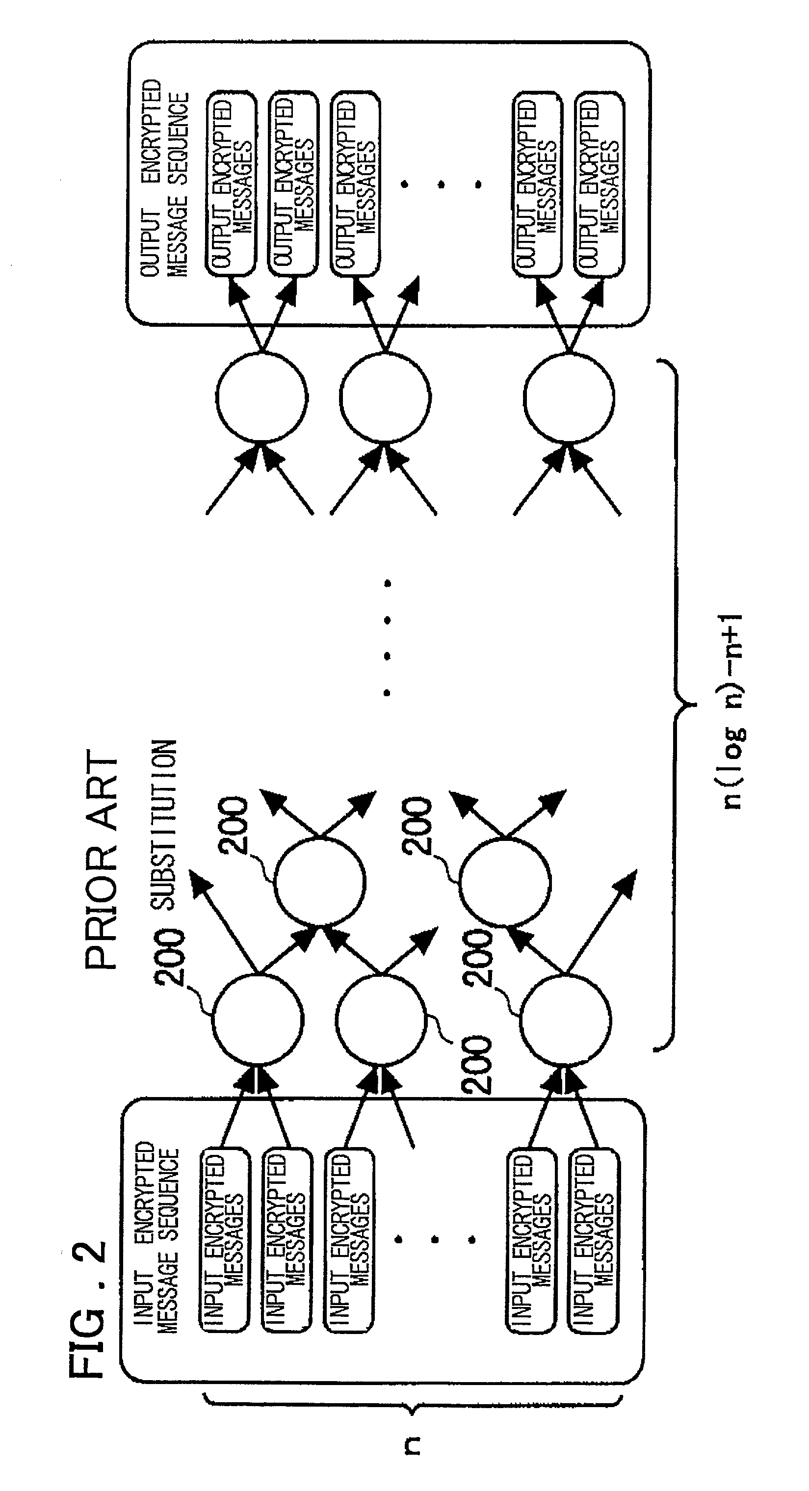
[0013]So, the computational resources is increased with the increasing number of the encrypted input messages.
[0014]It is therefore an object of the present invention to provide a method and a system in which the required computational resources for proving can be diminished without dependency on the number of encrypted input messages, and a program product.
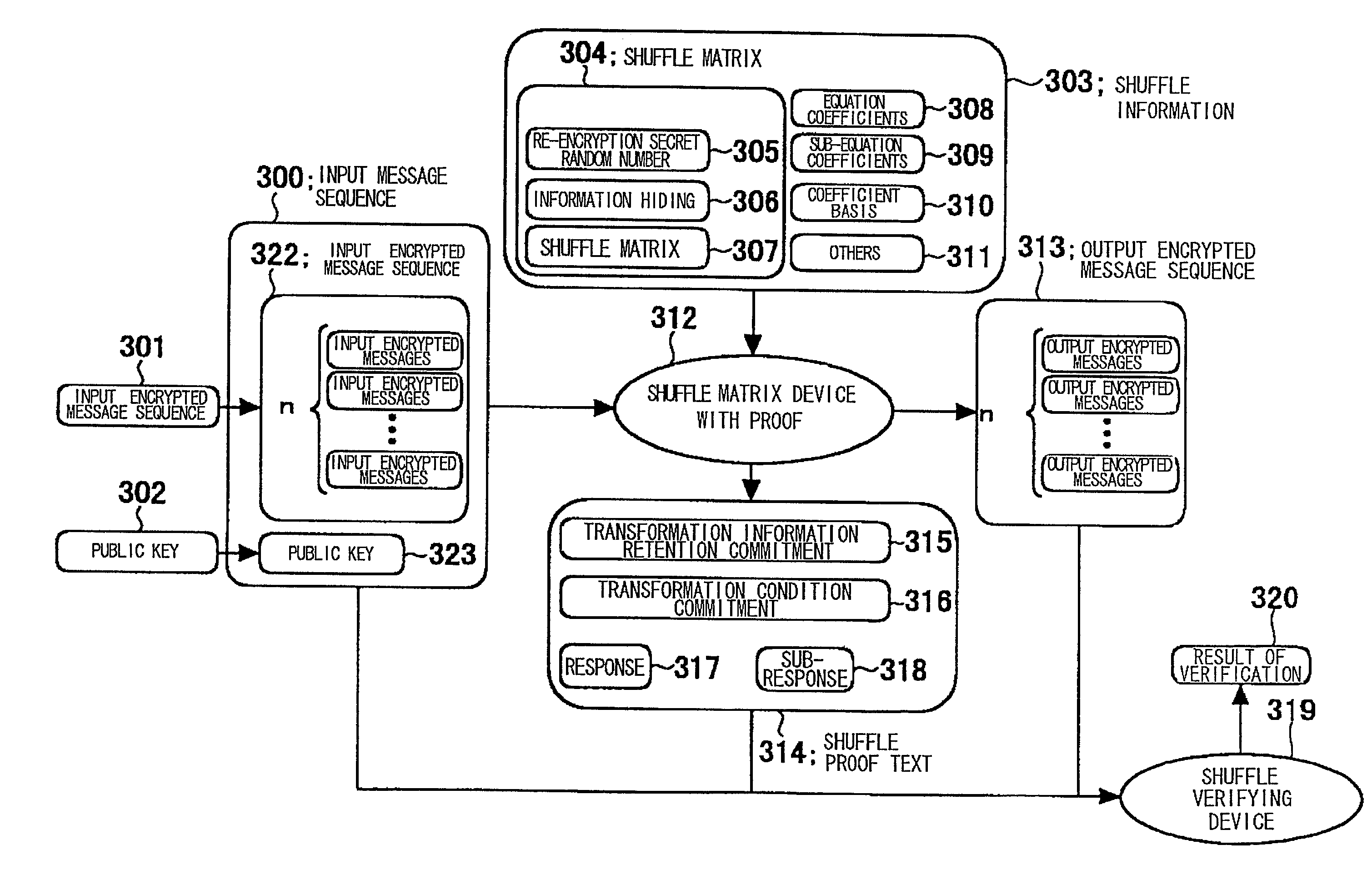
[0065]These two proofs are each simpler than the proof of the conventional shuffle such that the computational resources is diminished without dependency on the number of the input encrypted messages. This asset is not lost in the proof of the shuffle consisting in the combination of the two proofs.

Problems solved by technology

Each shuffling is in need of computation which consume large amount of computational resource involving modular exponentiation twice as many as the number of re-encrypted input messages.
On the other hand, verification is in need of computation which consume large amount of computational resource involving modular exponentiation twice as many as the number of re-encrypted input messages.

Method used


Image

  • Method and apparatus for shuffle with proof, method and apparatus for shuffle verification, method and apparatus for generating input message sequence and program for same
  • Method and apparatus for shuffle with proof, method and apparatus for shuffle verification, method and apparatus for generating input message sequence and program for same
  • Method and apparatus for shuffle with proof, method and apparatus for shuffle verification, method and apparatus for generating input message sequence and program for same

Examples


embodiment 1

[0190]Referring to FIGS. 4 and 5, the shuffle method with proof, and a verification method, according to Embodiment 1 embodying the Present invention, are explained. Meanwhile, ┌ is assumed to be 0, 1.

[0191]As the shuffle information 401, the permutation matrix 402, coefficient basis 404 and the generator coefficient 403 are prepared as follows:

[0192]As for the permutation matrix 402, numbers of 1 to n are arrayed in order. A Pseudo random number generator, not shown, is used n times to generate n sequences of numbers and an ith number of each number sequence is divided by n−i+1 to find a remainder which is set to π′(i).

[0193]It is noted that i is in the order from 1 to n, with the π′(i) th number counted from the lower side of the number sequence being set to π(i). The operation of removing this number from the number sequence is executed to determine π (i); i=1, . . . , n. The ith row of the shuffle matrix is 1 only for the component of the π(i) column with the remaining values be...

embodiment 2

[0221]Referring to FIGS. 6 and 7, the shuffle method with proof and the verifying method therefor according to Embodiment (2) of the present invention are explained. In the following, it is assumed that ┌=0, 1.

[0222]As the shuffle information 601, the shuffle matrix 602, element coefficients 603, coefficient basis 604, 605 and sub-equation coefficient 606 are prepared as follows:

[0223]As for the shuffle matrix 602, it is generated in the same way as in the Embodiment (1) described above.

[0224]As for the element coefficient 603ρ′, ρ″, coefficient basis 604 v, coefficient basis 605 v, sub-equation coefficient 606, λ[μ]; μ=0, . . . , n, a number other than 1, 0 on Fq is generated for ρ′, ρ″λ[μ]; μ=0, . . . , n. while an element of Fp of an order number q is generated for the coefficient basis u, v:

ρ′∈RFq, ≠0, 1

ρ″∈RFq, ≠0, 1

v∈RF*p, ≠1, s.t. vq=1 / F*p

λ[μ]∈RFq, ≠0, 1, μ=0, . . . , n

u∈RF*p≠1, s.t.uq=1 / F*p

[0225]From the input encrypted message sequence and from the public key, an input messa...

embodiment 3

[0242]As an Embodiment (3) of the present invention, the shuffle method with proof and the corresponding verifying method are explained with reference to FIGS. 8 and 9. It is assumed that ┌=0, 1, and that there are two sets of the public keys, namely η[−1, ┌], η[0, ┌]; ┌=0, 1, both having the same secret key.

[0243]As the shuffle information 801, the shuffle matrix 802, element coefficients 803, 805, coefficient basis 804, 806 and the sub-equation coefficient 807 are prepared as follows:

[0244]The shuffle matrix, used in the preferred embodiment, differs in size from those of the Embodiment (1) and (2), and is a n+2 rows by n+1 column matrix.

[0245]The permutation matrix, constituting this shuffle matrix 802, is A[i, j]; i, j=1, . . . , n, with the re-encryption secret random number being 2×n components of A[−1, j], A[0, j]; j=1, . . . , n, with the knowledge hiding factor being n+2 components of A[μ, 0]; μ=−1, . . . , n. These components are generated in a similar manner to Embodiment...


PUM


Abstract

A shuffle with proof having a method for proof generating with small computational resources proportionate to the number of input encrypted messages and a corresponding method for verification. Shuffle is represented by a generalized transformation. Combining a proof that the transformation information is retained and a proof of a condition under which the transformation is met constitute the proof for shuffle. The two proofs are short proportional to the number of input encrypted messages. Transformation information retention is proved in such a manner that, since the response is generated from challenge value in dependency upon transformation, the condition under which the transformation is met is reflected in the response-challenge value relation. If the condition under which the transformation corresponding to the shuffle is selected as the condition for proof, the two proofs may constitute the proof for shuffle.

Description

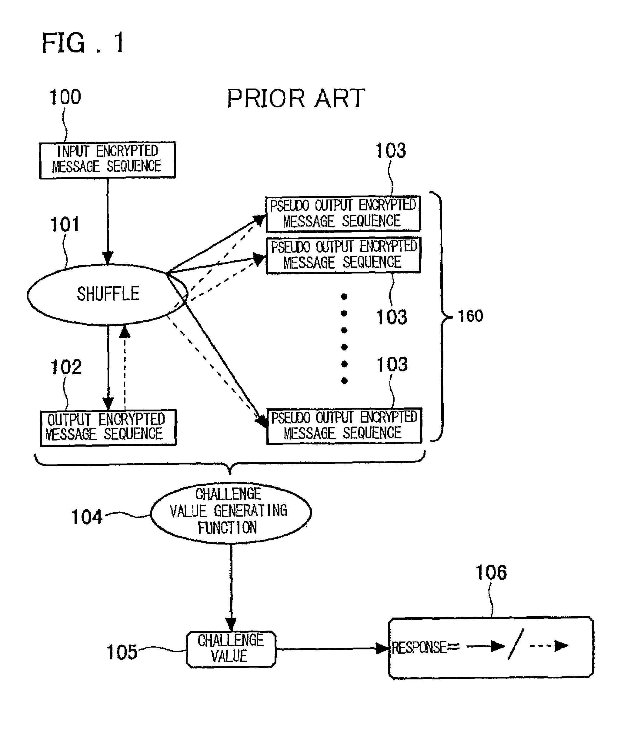
FIELD OF THE INVENTION[0001]This invention relates to a technique for shuffle for guaranteeing the presence of one-to-one correspondence between input and output encrypted messages, such as is used in constructing an anonymous communication path, as the one-to-one correspondence is kept confidential, and to a technique of verifying the shuffle.BACKGROUND OF THE INVENTIONBackground Art (1)[0002]As for the background art for shuffle with proof, reference is had to e.g., the JP Patent Kokai JP-A-08-263575 (publication 1). FIG. 1 shows the structure described in this publication 1. Meanwhile, in the drawings of the present application, confluent arrows indicate that the information corresponding to the originating point of the arrows are all collected and sent to a location corresponding to the points of the respective arrows, whilst diverging arrows indicate that all or part of the information at the originating points of the arrows are sent to a location corresponding to the points of...

Claims


Application Information

Patent Timeline
Patent Type & Authority Patents(United States)
IPC IPC(8): H04K1/00H04L9/00G09C1/00G09C1/04H04L9/08H04L9/30H04L9/32
CPCH04L9/3271H04L9/3093H04L9/3218H04L9/3013
Inventor FURUKAWA, JUN
Owner NEC CORP
Why Eureka
Try Eureka