Heat storage apparatus with spiral electrically heated phase change material

a phase change material and heat storage technology, applied in the direction of lighting and heating apparatus, indirect heat exchangers, stationary plate conduit assemblies, etc., can solve the problems of difficult to obtain a high performance as a whole, difficult to achieve stable output, and easy to overheat, so as to achieve high reliability and low cost , the effect of high reliability

Inactive Publication Date: 2006-04-25
HONDA MOTOR CO LTD
View PDF14 Cites 20 Cited by
  • Summary
  • Abstract
  • Description
  • Claims
  • Application Information

AI Technical Summary

Benefits of technology

[0029]In the event that the lead patterns are provided on at least one of the lids and intermediate plate, a highly reliable wiring can be installed at low costs. In addition, in the event that the spiral pattern is included in the lead patterns, since the spiral pattern is allowed to function as an inductance, power factor can be attempted to be improved.

Problems solved by technology

1) Since a number of fluid passageways each having a quadrangular shape exist alternately, it is difficult to allow a heat exchanging fluid to flow into all the fluid passageways uniformly, and there happen to be caused locations where the heat exchanging fluid flows in such a large amount that heat exchanging is completed so quickly and, on the contrary, locations where the heat exchanging fluid flows in such a small amount that heat exchanging is not promoted, thereby making it difficult to obtain a high performance as a whole.
2) Since a number of quadrangular heat storage material accommodation cells exist alternately, the volume of each heat storage material accommodation cell becomes small, and therefore, when heat is taken out of the phase changeable heat storage material, an excessively cooling phenomenon is easy to occur, and therefore, a stable output cannot be obtain.
However, the lead wire 102 needs to be drawn out from each electrode plate 101, and taking for example a case shown in FIG. 14, since the phase changeable material 4 is accommodated in 16 cells which are partitioned in a 4×4 fashion, 32 lead wires 102, which results from 16×2, need to be drawn out as a whole, and since such a large number of lead wires 102 need to be laid out, the production cost of the apparatus is increased and the feed control becomes difficult.
The layout of electric wires becomes complex very much, and this increases the number of components involved, as well as the production costs.

Method used


Image

  • Heat storage apparatus with spiral electrically heated phase change material
  • Heat storage apparatus with spiral electrically heated phase change material
  • Heat storage apparatus with spiral electrically heated phase change material

Examples


Embodiment Construction

[0045]An embodiment of the invention will be described below based on the accompanying drawings. Note that the drawings are to be seen in directions in which reference numerals are oriented.

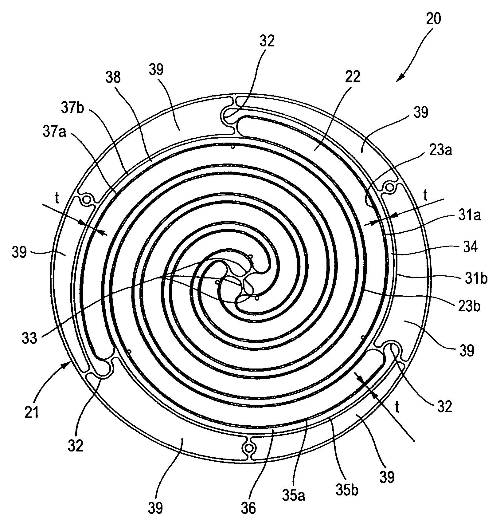
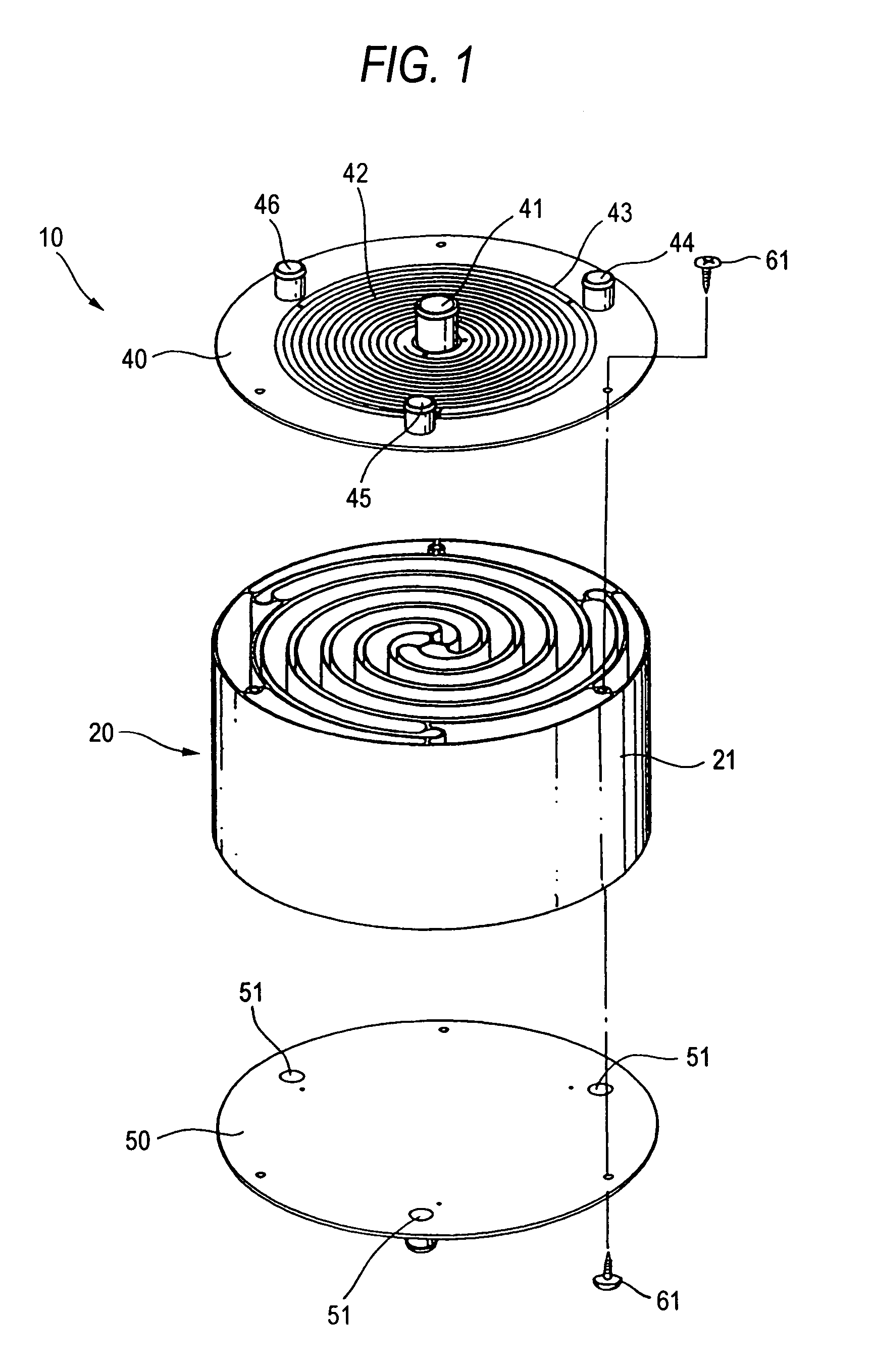
[0046]FIG. 1 is an exploded perspective view of a heat storage apparatus according to the invention, and the heat storage apparatus 10 includes a cylindrical heat storage main body 20, a top lid 40 placed to cover a top side of the heat storage main body 20, a bottom lid 50 placed to close a bottom side of the heat storage main body 20 and retaining machine screws 61 . . . ( . . . denotes plurality).

[0047]A fluid inlet 41 for a heat exchanging fluid is provided in the center of the top lid 40, and a spiral lead pattern 42 is provided in such a manner as to surround the fluid inlet 41. Then, a ring-like lead pattern 43 is provided in such a manner as to surround the spiral lead pattern 42, and three heat storage material injecting ports 44, 45, 46 are provided in such a manner as to surround the r...


PUM


Abstract

A heat storage apparatus comprises a heat storage material accommodation cell for accommodating therein a heat storage material having an electricity conductive characteristic and configured to be electrically heated, and a fluid passageway for allowing a heat exchanging fluid to flow therethrough, the fluid passageway being adjacent to the heat storage material accommodation cell via a bulkhead. The heat storage material accommodation cell and the fluid passageway are put in a spiral configuration together with the bulkhead in a heat storage main body of the heat storage apparatus. Heat held in the heat storage material is transferred to the heat exchanging fluid so as to be taken out of the heat storage apparatus.

Description

BACKGROUND OF THE INVENTION[0001]1. Field of the Invention[0002]The present invention relates to a heat storage apparatus of a type in which heat energy is taken out from a heat storage material which is electrically heated by a heat exchanging fluid.[0003]2. Description of the Related Art[0004]In recent years, a demand has been increasing that heat is stored using inexpensive power available late at night so that heat energy so stored is taken out for use in supplying hot water and heating rooms during the daytime, and in association with such a demand, there has been a tendency that high-performance heat storage apparatuses are demanded.[0005]A heat-storage type heat exchanger is known as a heat storage apparatus in the related art (for example, in JP-A-11-264683 (paragraph [0012], FIG. 1)).[0006]The related art will be described by reference to FIGS. 1A, 1B in the patent literature No. 1.[0007]FIG. 13 is a drawing incorporated herein to illustrate what is illustrated in FIG. 1B o...

Claims


Application Information

Patent Timeline
Patent Type & Authority Patents(United States)
IPC IPC(8): F28D7/04F24H1/00H05B1/00F24H7/04F28D9/04F28D20/02
CPCF24H7/0408F28D20/02F28D9/04Y02E60/145Y02E60/14
Inventor KUDO, TOMOHIDE
Owner HONDA MOTOR CO LTD
Why Eureka
Try Eureka