
Mixed language simulator

a simulator and language technology, applied in the field of mixed language simulators, can solve the problems of difficult to learn, inconvenient for simple applications, slow and more complex than using pli, and difficult to learn and use thread packages, etc., to achieve the effect of improving the interfa

Inactive Publication Date: 2006-04-25
SYNOPSYS INC
View PDF6 Cites 38 Cited by
  • Summary
  • Abstract
  • Description
  • Claims
  • Application Information

AI Technical Summary

Benefits of technology

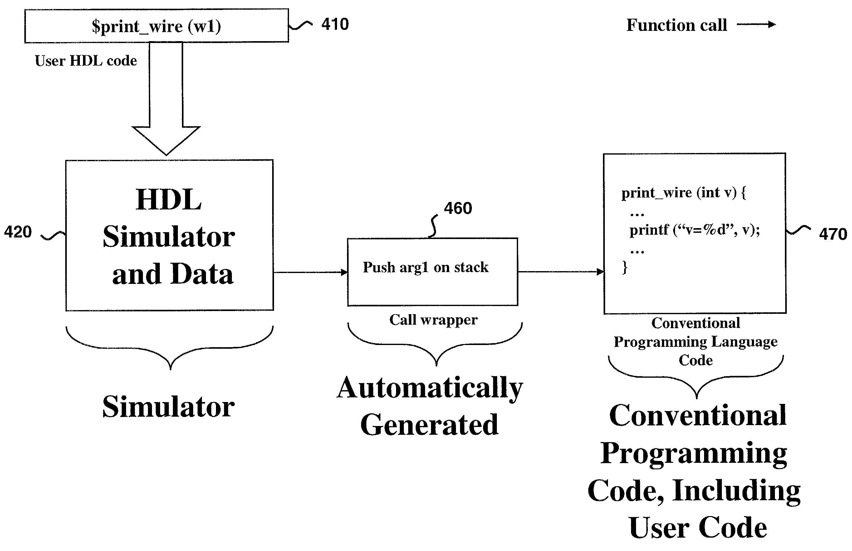
[0018]The invention achieves these and other objects by providing an HDL simulator, which uses either compiled or interpreted HDL code, and comprises an automated interface to compiled or interpreted application code written in a general purpose programming language. The interface enables the HDL code to have a direct data access to and from the application code. The simulator automatically maps and converts HDL data types to and from programming language data types, such as the arguments of routine calls or direct data accesses. Further, the simulator provides a programming language calling mechanism and automatically does data type mapping of arguments, which enables the HDL to call application code routines compiled with a standard compiler, and enables such routines to call functions in the HDL. The simulator automatically generates wrappers for the interface which automatically map data types for direct data access when the application code is compiled, and can output messages upon the occurrence of calls or returns. The automatically generated wrappers also provide automatic threading, which enables compiled application code to call tasks in the HDL.

Problems solved by technology

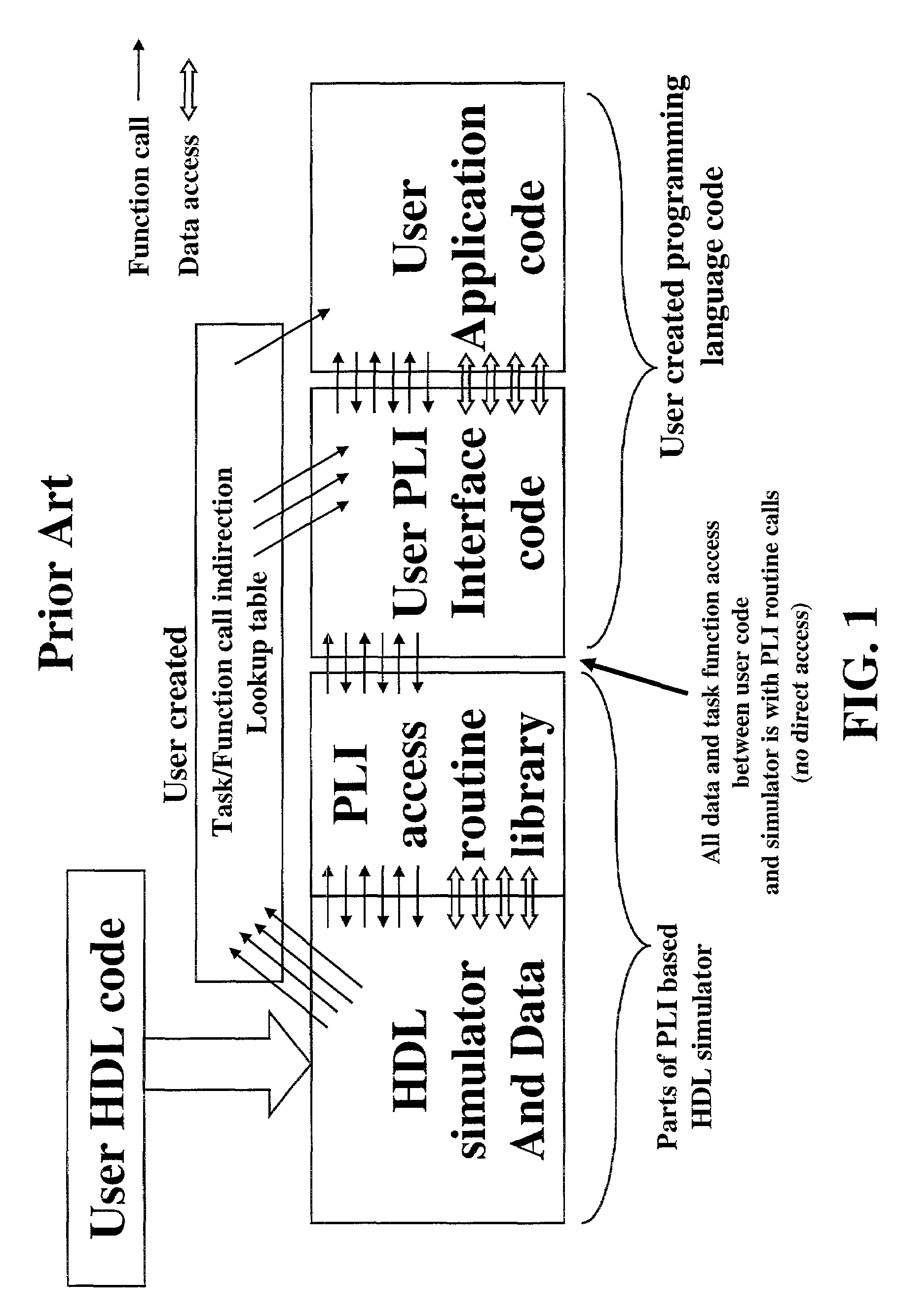
Hardware design or verification engineers modeling a complex digital system often find that different modeling languages have both strengths and weaknesses in implementing the desired model.
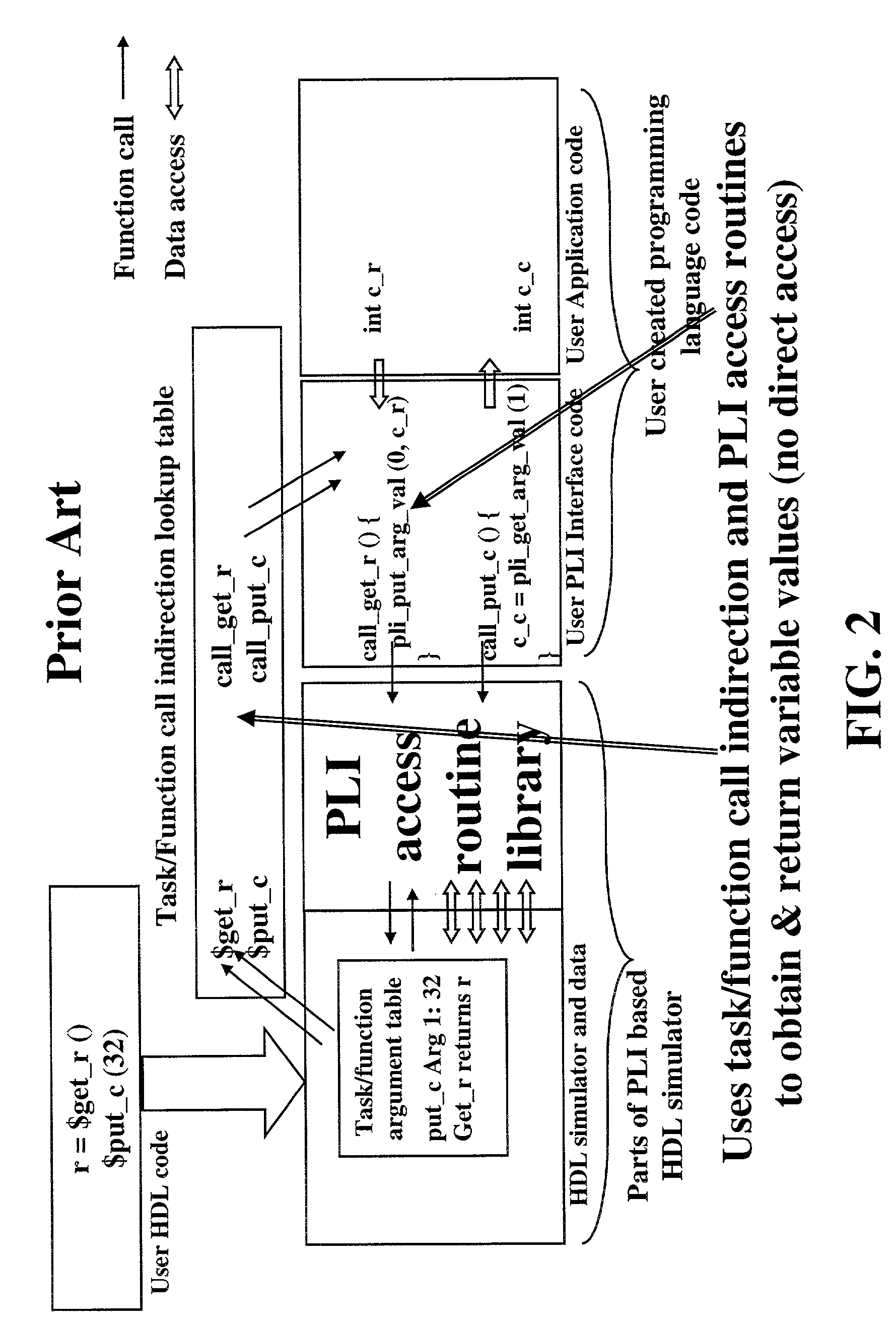
Such PLI programming is complex, difficult to learn, and inappropriate for simple applications.
This is even slower and more complex than using the PLI, and its use has been primarily in so-called “co-verification” products.
These thread packages are hard to learn and use.

Method used


Image

  • Mixed language simulator
  • Mixed language simulator
  • Mixed language simulator

Examples


Embodiment Construction

[0039]The present invention provides a mixed language simulator, referred to herein as a ‘blending simulator.’ which blends one or more HDLs with one or more conventional programming languages in an integrated programming environment. The blending simulator allows code to be read and integrated from a number of language sources, including HDLs, programming languages and linked shared objects from programming languages. The blending simulator is a substantial improvement over using PLI between Verilog and C or C++, for example.

[0040]The blending simulator, shown in FIG. 4, allows direct calling between an HDL, such as compiled or interpreted Verilog, and a compiled or interpreted programming language. This eliminates the need for users to program their own interfaces using PLI. The user HDL code 410 runs on the HDL simulator and data subsystem 420. User application code 470 may interact directly with the HDL simulator and data subsystem 420 through direct data access means 430. The t...


PUM


Abstract

An HDL simulator having an automated interface to compiled or interpreted application code written in a general purpose language. The interface enables the HDL code to have a direct data access to and from the application code. The simulator automatically maps and converts HDL data types to and from programming language data types, such as the arguments of routine calls or direct data accesses. Further, the simulator provides a programming language calling mechanism and automatically does data type mapping of arguments, which enables the HDL to call application code routines compiled with a standard compiler, and enables such routines to call functions in the HDL. The simulator automatically generates wrappers for the interface which automatically map data types for direct data access when the application code is compiled, and can output messages upon the occurrence of calls or returns. The automatically generated wrappers also provide automatic threading, which enables compiled application code to call tasks in the HDL.

Description

[0001]This application claims the benefit of U.S. Provisional Application No. 60 / 173,862, entitled “Mixed Language Simulation Environment,” filed on Dec. 30, 1999, and of U.S. Provisional Application No. 60 / 196,225, entitled “Mixed Language Simulation Environment,” filed on Apr. 10, 2000, the subject matter of which is incorporated herein by reference.BACKGROUND OF THE INVENTION[0002]1) Technical Field[0003]This invention relates to using a hardware description language (HDL) such as Verilog or VHDL in conjunction with a conventional programming language such as C, C++ or for performing the logical simulation of digital electronic systems.[0004]2) Discussion of the Prior Art[0005]Hardware design or verification engineers modeling a complex digital system often find that different modeling languages have both strengths and weaknesses in implementing the desired model. For example, an HDL, such as Verilog, may be well suited for describing specific hardware structures and behaviors, w...

Claims


Application Information

Patent Timeline
IPC IPC(8): G06F17/50
CPCG06F17/5022G06F30/33
Inventor FLAKE, PETERDAVIDMANN, SIMONHALL, MATTHEWKENNEY, JAMES
Owner SYNOPSYS INC
Learn More