System and method for multi-phase system development with predictive modeling

Inactive Publication Date: 2006-04-25
X ACT SCI INC
View PDF48 Cites 114 Cited by
  • Summary
  • Abstract
  • Description
  • Claims
  • Application Information

AI Technical Summary

Benefits of technology

[0026]FIG. 13 is a flow diagram of a process for improving the accuracy of

Problems solved by technology

With traditional system engineering, dynamic characteristics and behavior are not addressed until late in the development process, if at all, where the improvement possibilities are more limited.
Thus, there is no guarantee that an information system, once deployed, will satisfy current and future business requirements, such as business-critical response time and throughput.
Furthermore, problem isolation and debugging becomes more complicated, resul

Method used


Image

  • System and method for multi-phase system development with predictive modeling
  • System and method for multi-phase system development with predictive modeling
  • System and method for multi-phase system development with predictive modeling

Examples


Example

[0027]A description of preferred embodiments of the invention follows.

[0028]Business solutions involve interactions among business components, including business workloads, business processes, and data stores, to solve the needs of business entities. Generally, the design of such information systems are constrained by a set of business requirements, which predefine certain performance criteria to make the business solution acceptable. Information systems implement business solutions by providing a technical infrastructure that supports the business workload, business processes, and data storage requirements of the solution.

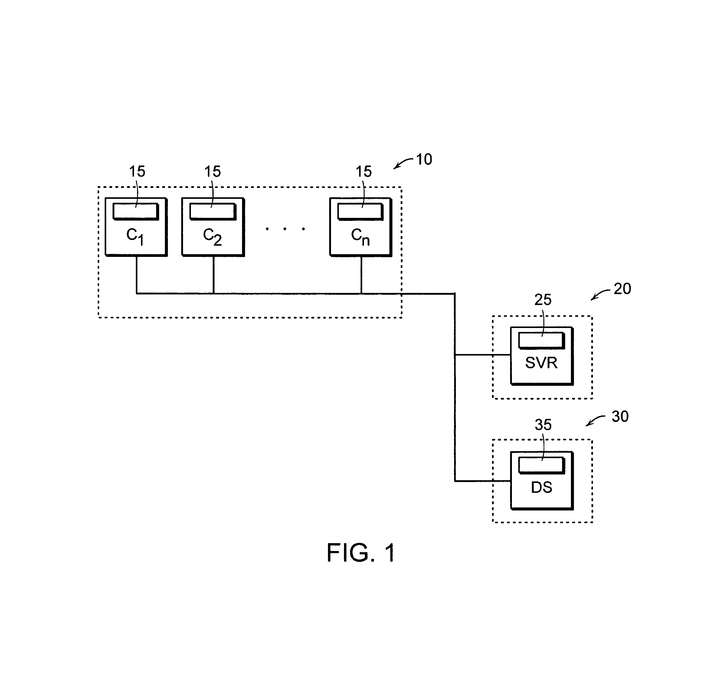
[0029]FIG. 1 is a diagram of a simple information system implementing a business solution according to one embodiment of the present invention. An information system typically includes a system architecture with software application components distributed across system hardware and system networking components. Referring to FIG. 1, the information system includes ...


PUM


Abstract

Information system designs and prototype implementation generated through one or more design and construction phases are validated utilizing predictive modeling. Design validation ensures that the design satisfies a set of performance requirements at each design phase, while validation of prototype implementation ensures the prototype behaves in conformance to the predictive model.

Description

RELATED APPLICATIONS[0001]This application is a continuation-in-part of application Ser. No. 09 / 127,191, filed Jul. 31, 1998, currently issued as U.S. Pat. No. 6,311,144 which claims the benefit of U.S. Provisional Application No. 60 / 085,350, filed on May 13, 1998. The entire teachings of the above applications are incorporated herein by reference.BACKGROUND OF THE INVENTION[0002]With the advent of electronic computing, business organizations have deployed computerized information systems to provide time-critical, cost-efficient business solutions. Information systems typically include various software applications distributed across one or more hardware / network operating environments.[0003]In developing such systems, traditional system engineering involves multiple development phases, including a requirements phase, an architecture design phase, a construction phase, and a deployment phase. During the design phases, static descriptions and assumptions about hardware and software co...

Claims


Application Information

Patent Timeline
IPC IPC(8): G06F13/10G06F17/10G06T11/20
CPCG06F17/10G06Q10/0633G06Q10/0639G06T11/206G06Q30/0201G06Q40/00G06Q10/06393
Inventor ABU EL ATA, NABIL A.ZELECHOSKI, PETER M.
Owner X ACT SCI INC
Why Eureka
Try Eureka