Method and program for obtaining positioning errors of printed-wiring board, and electronic-circuit-component mounting system

a technology of electronic circuit components and positioning errors, which is applied in the direction of manufacturing tools, semiconductor/solid-state device testing/measurement, instruments, etc., can solve the problems of inability to obtain the positioning errors of the printed wiring board relative to each component mounting unit, mechanical positioning devices limited in the positioning accuracy of the printed wiring board, and inability to achieve sufficient improvement of the mounting accuracy of electronic circuit components, so as to minimize the increase in the cost of manufacture. , the effect of improving the positioning accuracy of electronic circui

Inactive Publication Date: 2006-05-02
FUJI CORP
View PDF7 Cites 30 Cited by
  • Summary
  • Abstract
  • Description
  • Claims
  • Application Information

AI Technical Summary

Benefits of technology

[0010]The present invention was made in view of the background situation described above. It is an object of the present invention to assure a sufficient improvement in the accuracy of positioning of electronic circuit components as mounted on a printed-wiring board, while minimizing an increase in the cost of manufacture of an electronic-circuit-component mounting system of a type wherein a plurality of component mounting units are concurrently operated to perform operations to mount the electronic circuit components on the printed-wiring board. This object may be achieved according to any one of the following modes of this invention in the form of a method of obtaining positioning errors of a printed-wiring board, an electronic-circuit-component mounting system, a program for obtaining the positioning errors of the printed-wiring board, an electronic-circuit-component mounting program, or an electronic-circuit-component mounting system. Each of the following modes is numbered like the appended claims and depends from the other mode or modes, where appropriate, for easy understanding of the invention. It is to be understood that the present invention is not limited to the technical features of the following modes or any combinations thereof. It is to be further understood that a plurality of elements or features included in any one of the following modes of the invention are not necessarily provided all together, and that the invention may be embodied with only selected one or ones of the elements or features described with respect to the same mode.
[0017]Where the relative positioning errors of the plurality of component mounting units are negligibly small, the positioning errors of the printed-wiring board relative to the specific coordinate systems of the individual component mounting units can be obtained with high accuracy, on the basis of the specific positions of the fiducial portion of the board in the specific coordinate systems which have been obtained in the specific-position obtaining step. Where the relative positioning errors of the component mounting units are comparatively large, on the other hand, it is desirable to first obtain the relative positioning errors of the component mounting units as described below, and obtain the positioning errors of the printed-wiring board on the basis of not only the obtained specific positions of the fiducial portion but also the obtained relative positioning errors of the component mounting units. In either of those cases, the positioning errors of the components (e.g., electronic-circuit components) as mounted on the printed-wiring board can be reduced by controlling the component mounting units while taking account of the obtained positioning errors of the printed-wiring board relative to the component mounting units.
[0032]The relative position between the adjacent two component mounting units can be easily detected by using the fiducial board the length of which is sufficient to extend through at least a part of the area of movement of the mounting head of each component mounting unit, and which has at least one board fiducial portion corresponding to the area of movement of the mounting head of each component mounting unit. Where the relative angular or rotational positioning errors between the adjacent two component mounting units are negligibly small, the relative position of the adjacent units can be obtained by recognition of only one board fiducial portion corresponding to the area of movement of the mounting head of each unit. Where the relative angular positioning errors are not negligibly small, the fiducial board is required to have at least two board fiducial portions corresponding to the area of movement of the mounting head of each unit, for accurately detecting the relative position.
[0034]Preferably, the fiducial portions of the printed-wiring board are fiducial marks provided on the printed-wiring board, while the recognition device is an imaging device operable to take images of the fiducial marks. Although the recognition device may be moved by an exclusive drive device, within the area of movement of the mounting head, the recognition device is preferably provided on the mounting head. Where the recognition device is provided on the mounting head, a system to obtain the positioning errors of the printed-wiring board can be simplified in construction and is available at a reduced cost. Further, the accuracy of detection of the positioning errors of the printed-wiring board can be improved in the absence of a drive device exclusively provided for moving the recognition device, since the detected positioning errors of the printed-wiring board would not be influenced by relative positioning errors between a drive device for the mounting head and the drive device for the recognition device.
[0040]In the component mounting method according to the above mode (9), the positions at which the printed-wiring board and the mounting heads are positioned relative to each other to mount the electronic circuit components on the board are compensated for the positioning errors of the board relative to the component mounting units, so that the positioning accuracy of the electronic circuit components as mounted on the board can be significantly improved.

Problems solved by technology

If the printed-wiring board has only one fiducial portion for each of the component mounting units, it is impossible to obtain the positioning errors of the board relative to each component mounting unit.
However, the mechanical positioning device is limited in the accuracy of positioning of the printed-wiring boards, and does not easily permit a sufficient improvement in the mounting accuracy of the electronic circuit components.
On the other hand, the board-holding device which is arranged to fixedly hold the printed-wiring board thereon and which is repositioned with high accuracy suffers from a problem of an inevitable increase in its structural complexity and an accordingly increased cost of its manufacture.

Method used


Image

  • Method and program for obtaining positioning errors of printed-wiring board, and electronic-circuit-component mounting system
  • Method and program for obtaining positioning errors of printed-wiring board, and electronic-circuit-component mounting system
  • Method and program for obtaining positioning errors of printed-wiring board, and electronic-circuit-component mounting system

Examples


first embodiment

[0141]The mounting head 144 and the fiducial-mark camera 148 are attached to the undersides of the respective arms 344, 346, such that a distance between the axis of rotation of the rotary member 340 and the gravity center of the mounting head 144 is substantially equal to a distance between the axis of rotation of the rotary member 340 and the gravity center of the fiducial-mark camera 148. The mounting head 144 and the fiducial mark camera 148 have the same constructions as in the

[0142]On the supporting member 349, there is also fixedly mounted a positioning device 360 provided to maintain hold or lock the rotary member 340 in one of two predetermined angular positions in which the arms 344, 346 extend in the longitudinal direction of the pivotal portion 322 of the pivotal member 314. Usually, the pivotal member 314 is held in a position in which the pivotal portion 322 extends in the Y-axis direction while the arms 344, 346 also extend in the Y-axis direction where the rotary mem...

second embodiment

[0159]In the present second embodiment, the host computer 280 provided commonly for all of the plurality of component mounting units 300 detects the relative positioning errors of the adjacent units 300 and the positioning errors of the printed-wiring board 12, and compensates the predetermined component mounting positions of the mounting heads 144. However, the computer 250 provided in each unit 300 may be assigned to effect at least one of the detection of the relative positioning errors of the adjacent units 300, the detection of the positioning errors of the board 12 and the compensation of the component mounting positions. In particular, it is effective to arrange the computer 250 to effect the compensation of the component mounting positions of the mounting head 144. While all of the plurality of component mounting units 300 are provided with the respective image-processing computers 272, a single common image-processing computer may be used commonly for all of the units 300.

third embodiment

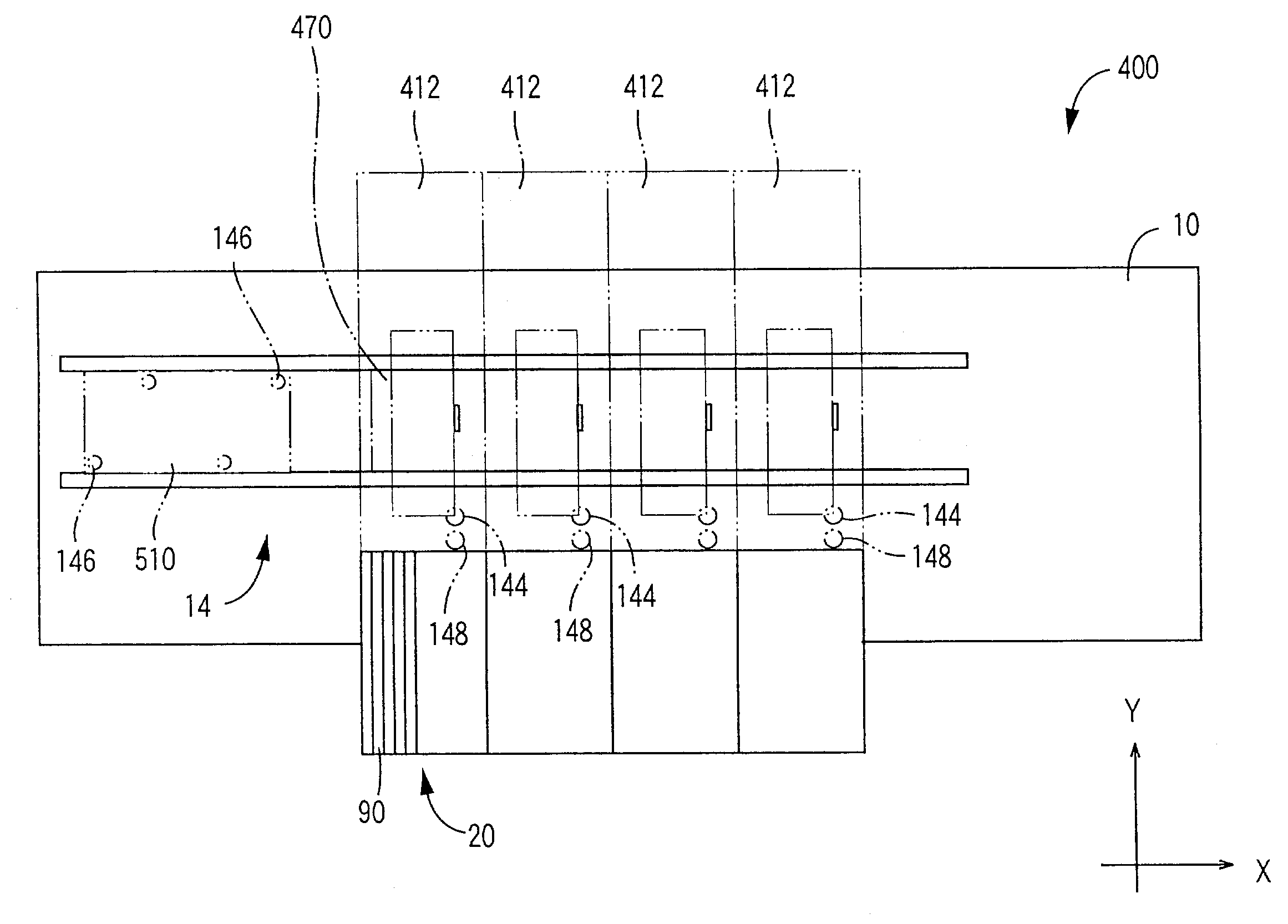
[0160]Referring to FIGS. 14–16, there will be described an electronic-circuit-component mounting system 400 constructed according to this invention. The present system 400 also includes the board conveyor 14 and the component supplying device 20 disposed on the machine base 410, and further includes a plurality of component mounting units 412 arranged at a predetermined spacing pitch in the X-axis direction or the feeding direction of the printed-wiring board 12.

[0161]As shown in FIGS. 15 and 16, each component mounting unit 412 includes an XY drive device in the form of an XY robot 442 held by a frame 446 which is supported by support columns 444 extending upwards from the machine base 410. To the underside of the frame 446, there are fixed a pair of parallel guide rails 448 extending horizontally in the Y-axis direction. A Y-axis slide 452 is held in slidable engagement with the guide rails 448 through a pair of guide blocks 450. The Y-axis slide 452 has a ballnut 454 fixed theret...


PUM

PropertyMeasurementUnit
areasaaaaaaaaaa
lengthaaaaaaaaaa
areaaaaaaaaaaa

Abstract

An electronic-circuit-component mounting system including at least two component mounting units concurrently operated to mount electronic circuit components on a printed-wiring board, wherein a relative position of the two units is obtained from positions of a common calibration mark fixed provided on machine base commonly for the two units, which positions are detected by fiducial-mark cameras of the two units, or obtained from positions of fiducial marks provided on a fiducial board, which positions are detected by the cameras while the fiducial board is located in alignment with component mounting areas of the two units, and wherein positioning errors of the printed-wiring board relative to the two units are calculated on the basis of the obtained relative position of the two units, and positions of at least two fiducial marks provided on the printed-wiring board, which positions are detected by the cameras of the two units.

Description

[0001]This application is based on Japanese Patent Application No. 2002-133032 filed May 8, 2002, the contents of which are incorporated herein by reference.BACKGROUND OF THE INVENTION[0002]1. Field of the Invention[0003]The present invention relates to an electronic-circuit-component mounting system arranged to mount a plurality of electronic circuit components on a printed-wiring board, a method practiced in this system to obtain positioning errors of the printed-wiring board, a method of mounting the electronic circuit components, and programs for practicing those methods.[0004]2. Discussion of Related Art[0005]There is known an electronic-circuit-component mounting system which includes a plurality of component mounting units arranged along a straight line. Each of the component mounting units is provided with a mounting head and a head moving device operable to move the mounting head. This electronic-circuit-component mounting system is arranged such that at least two of the co...

Claims


Application Information

Patent Timeline
Patent Type & Authority Patents(United States)
IPC IPC(8): H05K3/30H05K3/00H05K13/04H05K13/00
CPCH05K13/0069H05K3/0008Y10T29/49117Y10T29/49131Y10T29/4913Y10T29/53178
Inventor KODAMA, SEIGO
Owner FUJI CORP
Why Eureka
Try Eureka