Apparatus and method for detecting low charge of working fluid in a waste heat recovery system

a technology of working fluid and low charge, which is applied in the direction of liquid degasification, instruments, separation processes, etc., can solve the problems of low charge, reduced plant efficiency and reliability, and damage to the turbin

Active Publication Date: 2006-05-02
RTX CORP
View PDF57 Cites 34 Cited by
  • Summary
  • Abstract
  • Description
  • Claims
  • Application Information

AI Technical Summary

Problems solved by technology

A low refrigerant charge condition may result in the pump reaching its maximum operating speed, after which point the thermal dynamic loop is no longer in control thereby causing serious problems, such as damage to the turbine due to reduced cooling capability because of high superheat.
The problems also include pump damage due to cavitations, reduction in plant efficiency, and reliability.
In addition, low charge condition also means undesirable emission of refrigerant gases into the environment.
They tend to be particularly unreliable for the application in waste heat recovery systems.

Method used


Image

  • Apparatus and method for detecting low charge of working fluid in a waste heat recovery system
  • Apparatus and method for detecting low charge of working fluid in a waste heat recovery system
  • Apparatus and method for detecting low charge of working fluid in a waste heat recovery system

Examples


Embodiment Construction

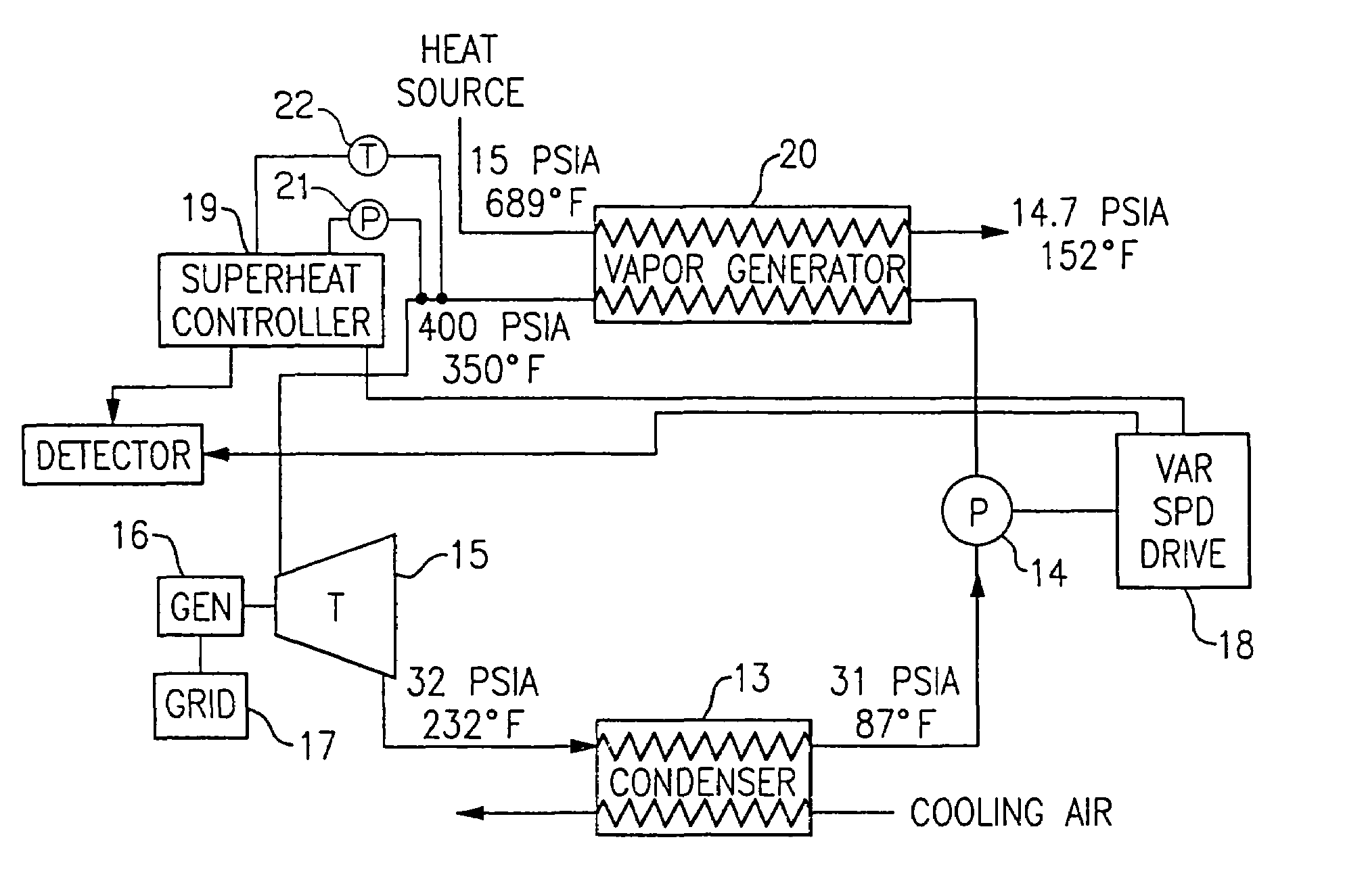
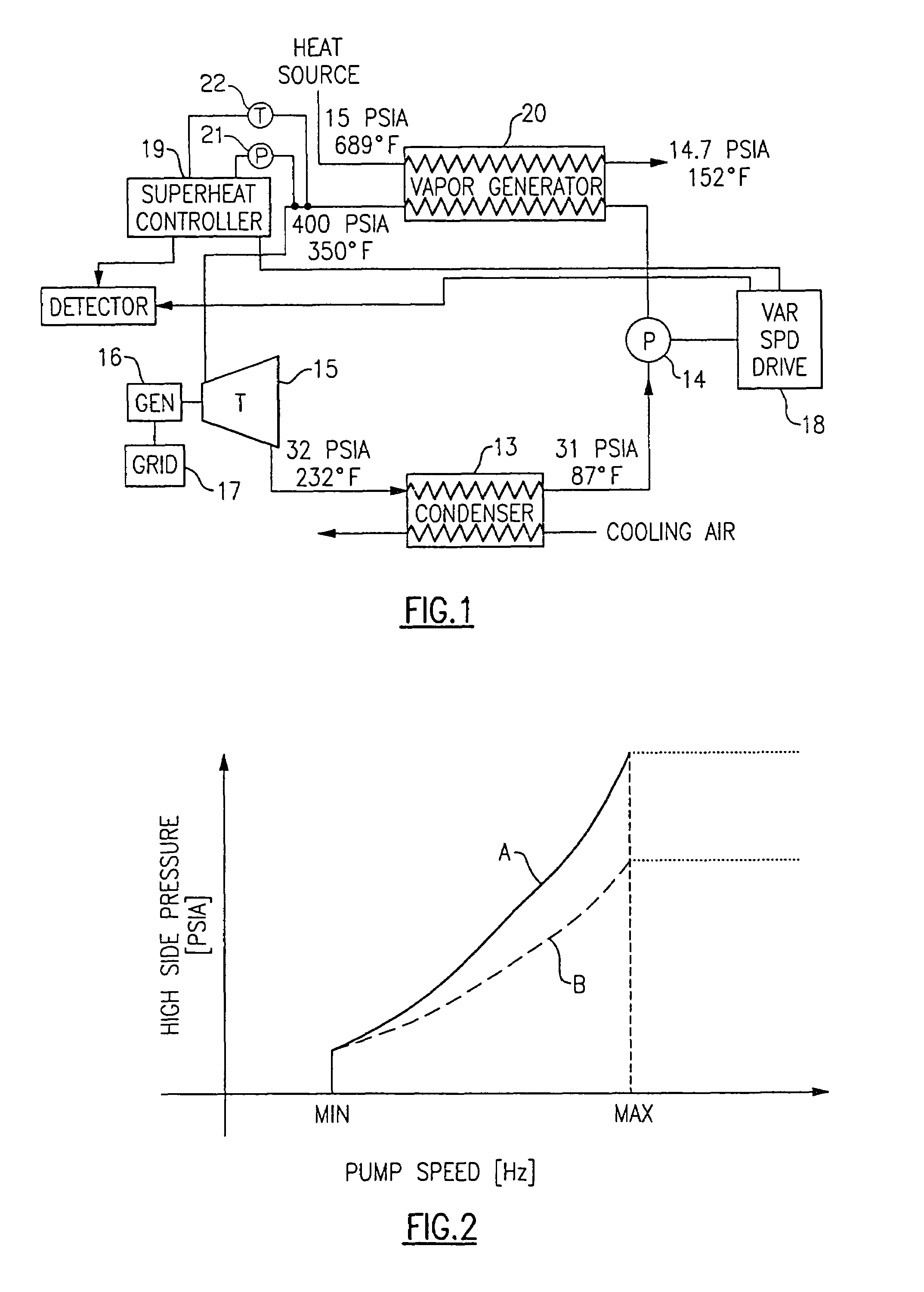
[0015]Referring now to FIG. 1, a waste heat recovery system is shown to include an organic rankine cycle (ORC) power plant that comprises, in serial flow relationship, a vapor generator 20, a turbine 15, a condenser 13, and a pump 14. The turbine 12 drives a generator 16 which generates power to be sent to a grid 17. The pump 14 is driven by a variable speed drive 18, with the speed thereof being controlled in a manner to be described more fully hereinafter.

[0016]Energy is provided to the ORC by way of the vapor generator 20, with the energy coming from a heat source which may otherwise transfer heat to the environment in the form of waste heat. An example of such a heat source is a mirco-turbine, with heat being given off at its exhaust and by its engine coolants. Typical pressures and temperatures are 15 psia and 689° F. for the fluid going into the vapor generator and 14.7 psia and 152° F. for the fluid being discharged from the vapor generator 20.

[0017]The working fluid being ci...


PUM

PropertyMeasurementUnit
temperaturesaaaaaaaaaa

Abstract

In a waste heat recovery system having a superheat controller, a reference superheat controller operating trajectory is established and compared with operational superheat controller trajectories from time to time and measuring the deviation therebetween to determine whether a low charge condition exists. If such a condition does exist, warning steps and possibly shut down steps can be taken. As a verification of a low charge condition, the absence or presence of oscillations in the pressure and / or pump power conditions can be observed.

Description

BACKGROUND OF THE INVENTION[0001]This invention relates generally to waste heat recovery systems and, more particularly, to a method and apparatus for detecting a low charge of working fluid therein.[0002]As used herein, the term “waste heat recovery system” includes distributed power generation systems, such as organic rankine cycle power plants, which use a pump to transport the refrigerant in the system. A typical waste heat recovery system includes an evaporator, a turbine, a condenser, and a pump. The evaporator absorbs heat from heat source, which causes the refrigerant in the evaporator to boil off into a gaseous state. The refrigerant flows from the evaporator outlet to a turbine, in which the refrigerant is expanded to a low pressure condition. From the turbine the refrigerant circulates first to a condenser, where the refrigerant is cooled to a liquid state, and then to a pump, after which the pressure is raised. From the pump, the refrigerant circulates back to the evapor...

Claims


Application Information

Patent Timeline
Patent Type & Authority Patents(United States)
IPC IPC(8): F02G1/00F01K23/10F01K25/08F02C6/18
CPCF01K23/101F02C6/18F01K25/08
Inventor KANG, PENGJUCOGSWELL, FREDERICK JAMES
Owner RTX CORP
Why Eureka
Try Eureka