
Micro-machined suspension plate with integral proof mass for use in a seismometer or other device

a technology of suspension plate and proof mass, which is applied in the direction of acceleration measurement using interia forces, instruments, material analysis, etc., can solve the problems of in-plane structure described in u.s. patent application ser, interference with accurate system operation over full bandwidth, and undesirable artifacts in amplitude and phase response of system

Inactive Publication Date: 2006-05-02
KINEMETRICS
View PDF18 Cites 11 Cited by
  • Summary
  • Abstract
  • Description
  • Claims
  • Application Information

AI Technical Summary

Benefits of technology

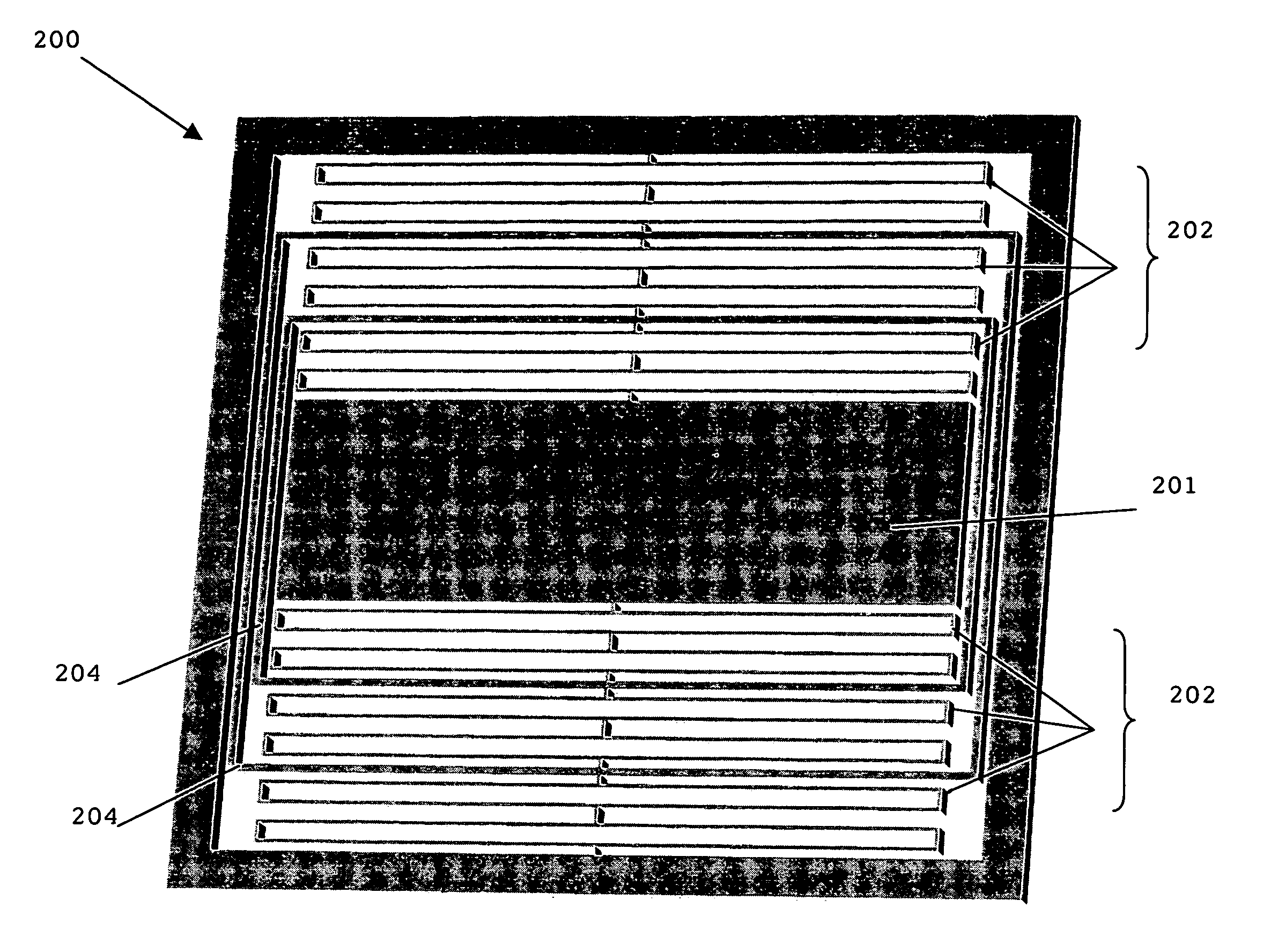
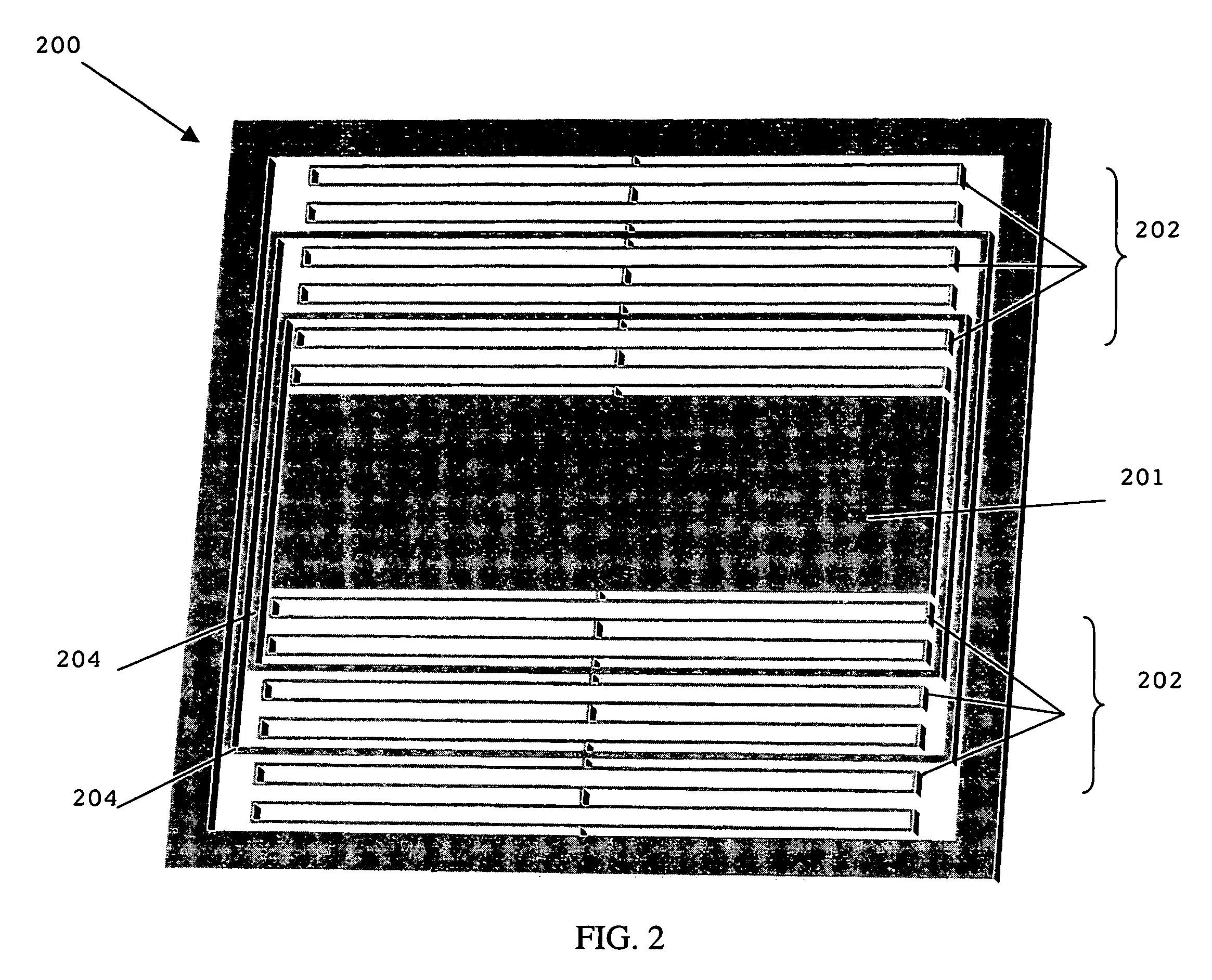
"The present invention improves upon a previous design by using intermediate frames to minimize off-axis motion of a proof mass and eliminate spurious modes over a wider bandwidth. The frames are placed between flexural elements to increase out-of-plane rigidity and minimize variation in transducer gap. The number of frames used is determined based on the desired bandwidth and operational parameters. The frames can include motion stops to prevent damage under overload conditions. A dampening structure is also included to provide damping during non-powered states. The damping structure includes a piston and cylinder or a dissipative material to slow down the outer intermediate frame. Overall, the invention produces a device with a flat response over a wide bandwidth."

Problems solved by technology

Otherwise, they will interfere with accurate operation of the system over the full bandwidth.
Unfortunately, many of these known techniques effect the geometry, placement and positioning of the drive and pick-up electrodes.
Moreover, while these techniques can allow for stable operation, they may still result in undesirable artifacts in the amplitude and phase response of the system.
Additionally, the in-plane structure described in U.S. patent application Ser. No. 10 / 058,210 may be fractured or damaged due to extreme external shock or vibration.
This problem occurs most often when the device is not powered and the feedback electronics are not active, in which case there is no active damping of the system.
Although the use of a gas-filled cavity may provide some damping effects, this alone may not be sufficient to minimize the effects of such external shock or vibration.

Method used


Image

  • Micro-machined suspension plate with integral proof mass for use in a seismometer or other device
  • Micro-machined suspension plate with integral proof mass for use in a seismometer or other device
  • Micro-machined suspension plate with integral proof mass for use in a seismometer or other device

Examples


Embodiment Construction

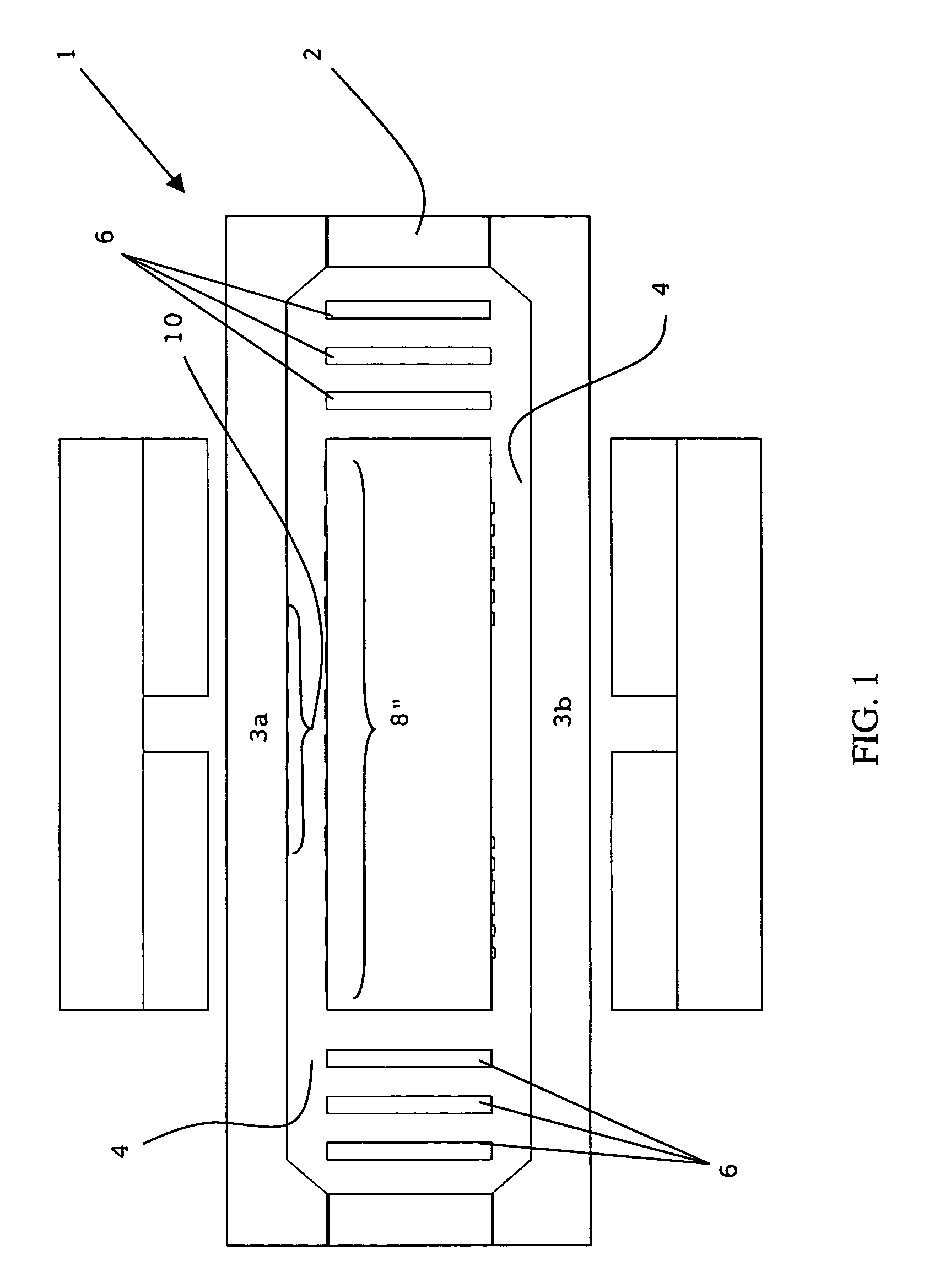
[0025]As explained earlier, U.S. patent application Ser. No. 10 / 058,210 entitled “MICRO-MACINED ACCELEROMETER” discloses an improved micro-machined suspension plate which may be utilized in an accelerometer, seismometer (velocimeter) and / or other similar device.

[0026]The suspension plate is formed of and includes a revolutionary, in-plane suspension geometry rather than a traditional—spring design. More particularly, the suspension plate is micro-machined to form a central proof mass and flexural elements located on opposite sides of the proof mass. FIG. 1 illustrates a cross-sectional diagram of a seismometer 1 having a suspension plate 2 and two capacitive plates 3a–b (alternatively, the device can have one capacitive plate), with a centrally located proof mass 8 supported by flexural elements 6 utilized in a known, prior-art micro-machined in-plane suspension geometry, as described and set forth in U.S. patent application Ser. No. 10 / 058,210.

[0027]As shown in FIG. 1, the proof ma...


PUM


Abstract

An accelerometer or a seismometer using an in-plane suspension geometry having a suspension plate and at least one fixed capacitive plate. The suspension plate is formed from a single piece and includes an external frame, a pair of flexural elements, and an integrated proof mass between the flexures. The flexural elements allow the proof mass to move in the sensitive direction in the plane of suspension while restricting movement in all off-axis directions. Off-axis motion of the proof mass is minimized by the use of intermediate frames disbursed within and between the flexural elements. Intermediate frames can include motion stops to prevent further relative motion during overload conditions. The device can also include a dampening structure, such as a spring or gas structure that includes a trapezoidal piston and corresponding cylinder, to provide damping during non-powered states.

Description

INCORPORATION BY REFERENCE[0001]This Application specifically incorporates by reference the subject matter and complete text and is a continuation-in-part of related patent application Ser. No. 10 / 058,210 entitled MICRO-MACHINED ACCELEROMETER” and filed on Jan. 25, 2002, now U.S. Pat. No. 6,776,042 as if set forth fully hereinafter.FIELD OF THE INVENTION[0002]The invention relates to seismic instrumentation in general. More particularly, the invention is related to an improved micro-machined suspension plate having an integral proof mass and a method of fabrication for the same that may be utilized in a seismometer (velocimeter), an accelerometer, or other similar device.DESCRIPTION OF THE PRIOR ART[0003]U.S. patent application Ser. No. 10 / 058,210 entitled “MICRO-MACHINED ACCELEROMETER”, was filed on Jan. 5, 2002 and discloses a novel construction of an accelerometer or seismometer using an in-plane suspension geometry having a suspension plate and at least one fixed capacitive plat...

Claims


Application Information

Patent Timeline
Patent Type & Authority Patents(United States)
IPC IPC(8): G01P15/125G01H11/00G01P15/08G01P15/13G01V1/18
CPCG01P15/08G01P15/0802G01P15/125G01P15/132G01V1/181G01P15/131G01P2015/0814G01P2015/082
Inventor PIKE, WILLIAM THOMASSTANDLEY, IANSYMS, RICHARD
Owner KINEMETRICS
Learn More