Differential unit

a technology of differential units and components, applied in the direction of bearing unit rigid support, bearings, transportation and packaging, etc., can solve the problems of imbalance with respect to drive pinion shafts, vibration affects vehicle body vibration, and spacers become unbalanced components. , to achieve the effect of reducing imbalan

Inactive Publication Date: 2006-05-02
SUBARU CORP
View PDF12 Cites 14 Cited by
  • Summary
  • Abstract
  • Description
  • Claims
  • Application Information

AI Technical Summary

Benefits of technology

[0010]The object of the present invention is to provide a differential unit that is capable of reducing an imbalance with respect to a drive pinion shaft.

Problems solved by technology

If the spacers are interposed between the bearings in this way, the longitudinal axis of the spacer is offset with the rotational axis of the drive pinion shaft, and the spacers become unbalanced components and imbalance arises with respect to the drive pinion shaft.
Because the spacers rotate integrally with the drive pinion shaft, vibrations will arise in the differential unit due to the above described imbalance if the drive pinion shaft rotates, and these transmission vibrations affect vehicle body vibrations.

Method used


Image

  • Differential unit
  • Differential unit
  • Differential unit

Examples


Embodiment Construction

[0023]Preferred embodiments of a differential unit of the present invention will be described in detail by referring to the following drawings. Omitted are the same reference numerals and repeated description.

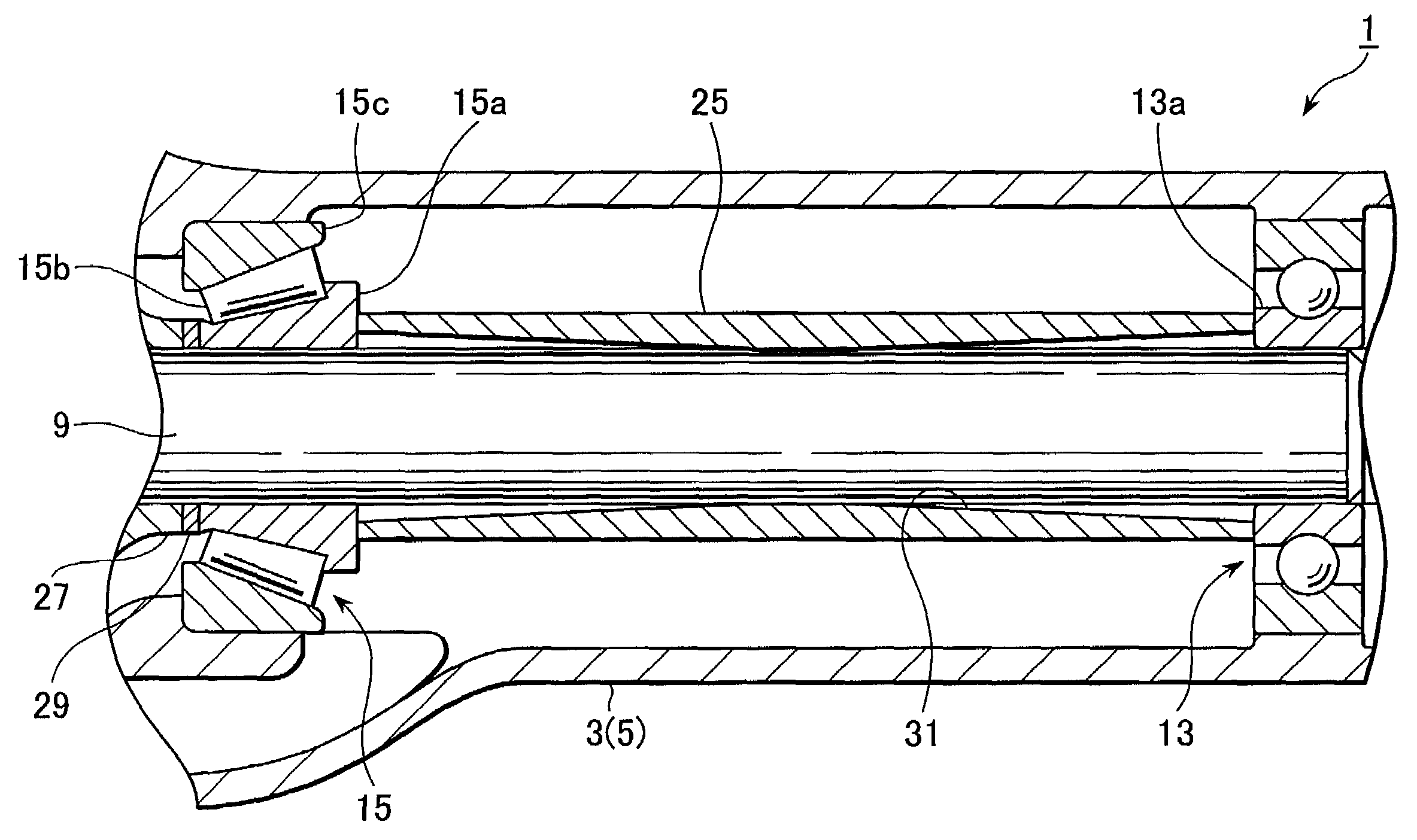
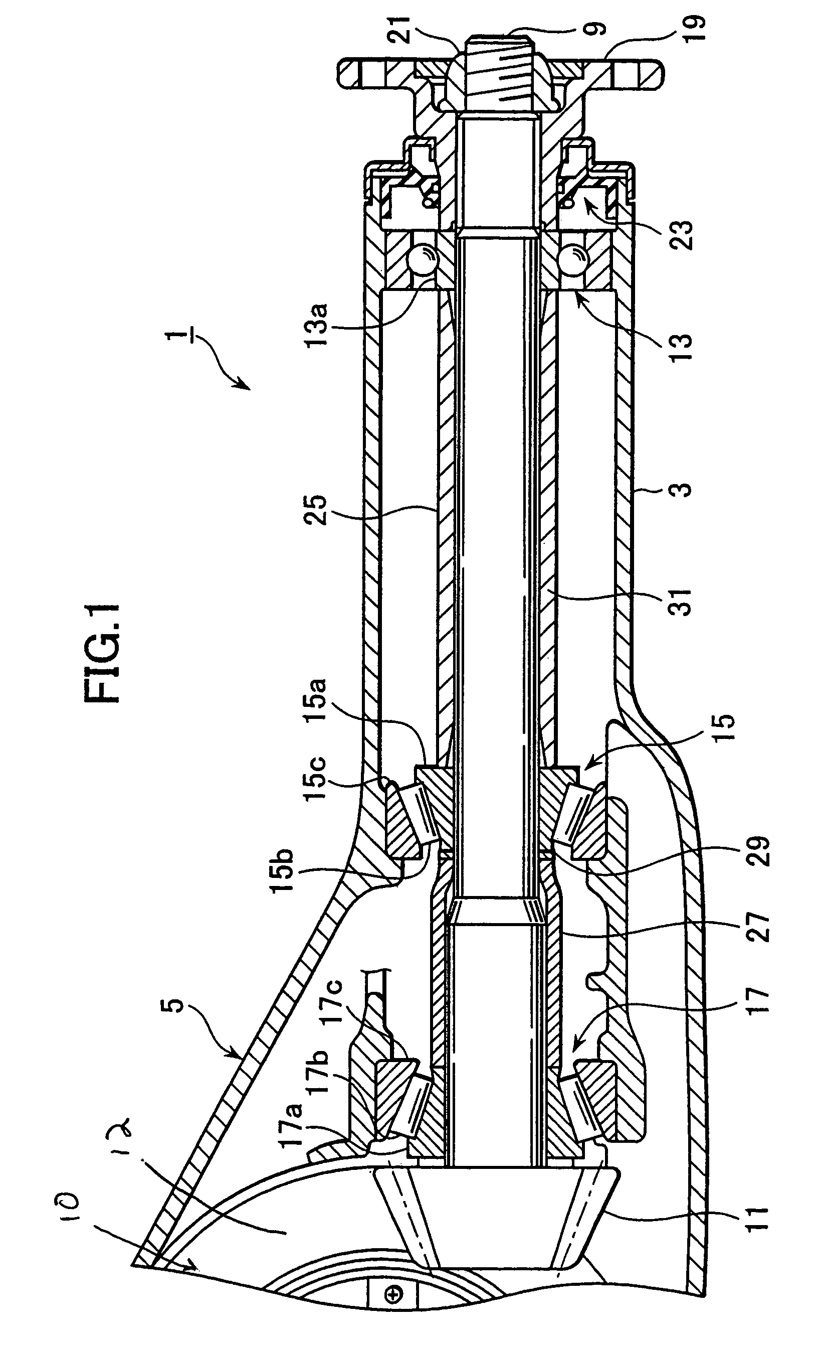
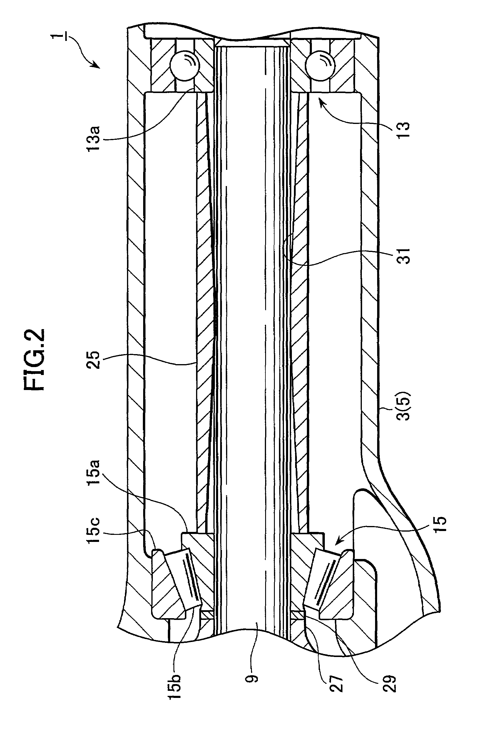
[0024]First, an embodiment of the differential unit according to the present invention will be described with reference to FIGS. 1 and 2. FIG. 1 is a schematic cross sectional drawing showing a differential unit of the embodiment, and FIG. 2 is a schematic cross sectional drawing of essential elements thereof shown in FIG. 1.

[0025]As shown in FIG. 1, the differential unit 1 has a case 5 including a differential carrier 3 and a cover (not shown) for closing an opening thereof. A drive pinion shaft 9 is accommodated in a part of the case 5. A drive pinion (bevel pinion) 11 integrally formed on one end of the drive pinion shaft 9, meshes with a driven gear 12 of a differential mechanism 10, which is rotatably supported in the differential carrier 3.

[0026]The drive pinion shaft 9 i...


PUM


Abstract

A protruding section facing a drive pinion shaft is integrally provided on (or provided as a separate component) a tubular spacer interposed between an inner race of a pilot bearing and an inner race of a tapered roller bearing at an inner section opposite to the drive pinion shaft. In one embodiment, a monolithic protruding section is curved so as to be convex along the overall central axial direction of the spacer, and is arch shaped in cross section. The protruding section protrudes towards the drive pinion shaft along the overall inner peripheral direction of the spacer, and the inner surface of the protruding section comes into contact with or close to the outer surface of the drive pinion shaft. Additional positions include one or a plurality of O-rings interposed between the drive pinion shaft and the inner surface of the tubular spacer.

Description

BACKGROUND OF THE INVENTION[0001]1. Technical Field[0002]The present invention relates to a differential unit.[0003]2. Related Art[0004]Generally, in a drive system for an automobile, a differential unit is used in order to change a transmitting direction of a drive power by ninety degrees, and to carry out a final gear reduction and a differential function.[0005]In the differential unit of the related art, as shown in FIG. 6, the differential unit 101 is provided with a drive pinion shaft 109 and a drive pinion (bevel pinion) meshing with a driven gear (not shown) at one end in a case 105 formed by a differential carrier 103 and a differential cover (not shown). The driven gear is rotatably supported in the differential carrier 103 by a differential mechanism (not shown) attached to the driven gear and by bearings (not shown), and mechanically connected to drive axles (not shown) for left and right wheels through the differential mechanism.[0006]The drive pinion shaft 109 is rotata...

Claims


Application Information

Patent Timeline
Patent Type & Authority Patents(United States)
IPC IPC(8): B60K17/24B60K17/16F16C19/54F16C35/06F16H48/08F16H48/38
CPCF16C19/54F16C35/061F16H57/021F16C19/49F16C19/546B60K17/16Y10T74/1967F16C2361/61Y10T74/19693F16H2048/423F16C35/06
Inventor TSUCHIYA, KENICHIHABARA, SEIJI
Owner SUBARU CORP
Why Eureka
Try Eureka