Container providing a controlled hydrated environment

a technology of hydrated environment and container, applied in the field of containers, can solve the problems of unsatisfactory shipping container type, difficult sipping of sipping water, and requiring training and skill,

a technology of hydrated environment and container, applied in the field of containers, can solve the problems of unsatisfactory shipping container type, difficult sipping of sipping water, and requiring training and skill,

US7036667B2Inactive Publication Date: 2006-05-02CAPLIPER LIFE SCI INC

Image

  • Container providing a controlled hydrated environment
  • Container providing a controlled hydrated environment
  • Container providing a controlled hydrated environment

Examples


Embodiment Construction

[0024]Specific embodiments of the present invention will now be described with reference to the figures, with like numbers indicating identical or functionally similar elements. A person skilled in the relevant art will recognize that other configurations and arrangements can be used without departing from the spirit and scope of the invention.

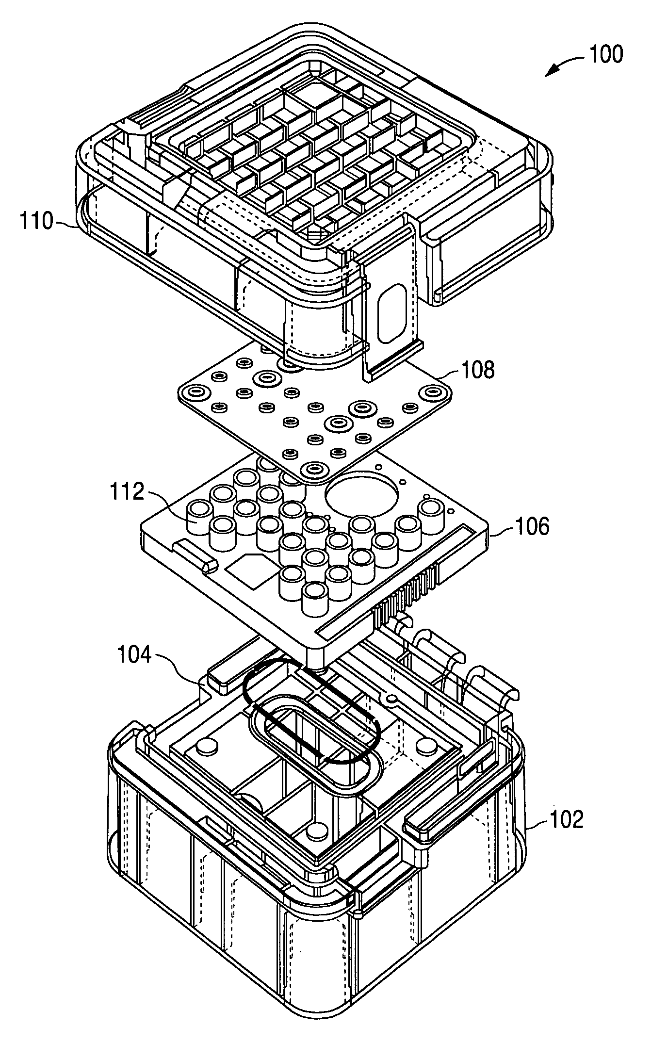
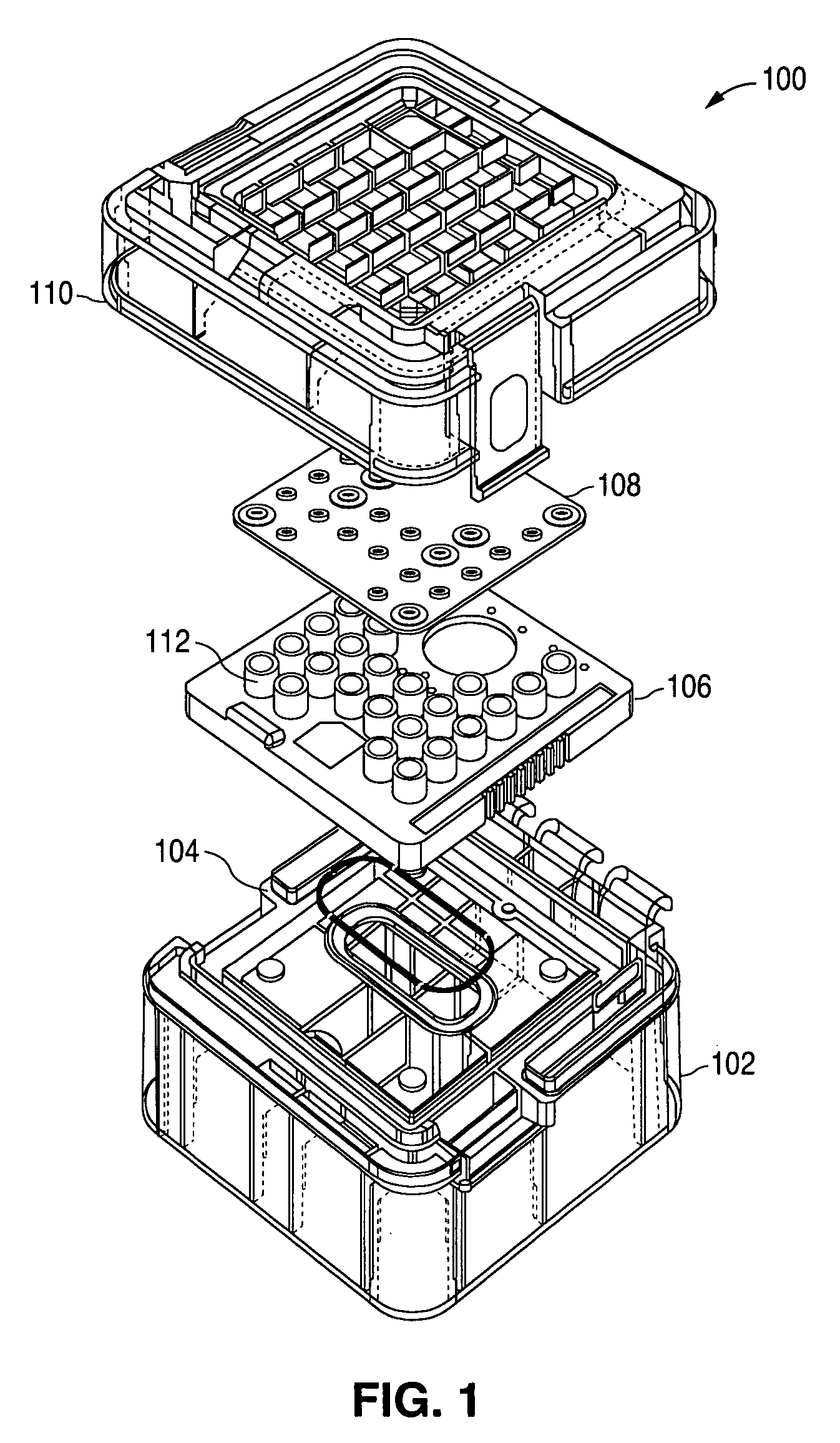
[0025]Referring now to FIG. 1, a first embodiment of the present invention is shown. Container 100 includes four basic parts: a base 102, an O-ring gasket 104, a cover gasket 108, and a cover 110. For the sake of clarity, microfluidic chip 106 is shown in situ, with at least one sipper located on one side of chip 106 (not shown), and a series of hydrated wells 112 on the other side of chip 106. Although container 100 is shown and intended to be used to house only one chip 106, container 100 may be readily modified to hold greater numbers of chips. For example, cover 110 could be adapted to act as both cover and base so that a series of contain...


PUM


Abstract

A container is provided for shipping and storing a pre-wetted and pre-conditioned microfluidic “sipper” chip. The container contains both dry compartments and wet compartments. A base contains a fluid-filled reservoir configured to house the capillaries. The opening of the reservoir is sealed with an O-ring. The plastic mount of the chip rests on the base in a dry compartment. The upper surface of the chip contains several wells containing fluid. A gasket is provided with plugs configured to be disposed within and seal the wells. Alternatively, the wells are first sealed with a foil film adhered to the well openings with an adhesive and a gasket is disposed between the foil and a cover, which is removably attached to the base. When the cover is closed, the gasket and O-ring seal the wet compartments to prevent leakage and to slow evaporation.

Description

CROSS-REFERENCE TO RELATED APPLICATIONS[0001]The present application also is a continuation-in-part of, and claims the benefit under 35 U.S.C. §120 of, U.S. application Ser. No. 10 / 449,517 filed Jun. 2, 2003. The disclosure of this referenced application is incorporated by reference herein in its entirety.BACKGROUND OF THE INVENTION[0002]1. Field of the Invention[0003]This invention relates generally to a container, and more particularly to a container that provides a controlled hydrated environment for the shipping and storage of microfluidic devices.[0004]2. Background of the Invention[0005]The use of microfluidic technology has been proposed for use in a number of analytical chemical and biochemical operations. This technology provides advantages of being able to perform chemical and biochemical reactions, macromolecular separations, and the like, that range from the simple to the relatively complex, in easily automatable, high-throughput, low-volume systems. The term, “microflui...

Claims


Application Information

Patent Timeline
02 May 2006
Publication
US7036667B2
IPC
B65D85/00; B01L9/00
CPC
B01L9/527; B65D85/70; B01L2200/025; B01L2200/185; B01L2300/041; B01L2200/0689
Inventors
GREENSTEIN, MICHAEL; KENNEDY, COLIN