Kite safety, control, and rapid depowering apparatus

a kite and rapid depowering technology, applied in the field of kite safety, control and rapid depowering apparatus, can solve the problems of no opportunity to regain kite spin out of control and crash, and quick de-powering of the kite, so as to increase the control of the kite, maintain control, and safe and quick de-powering the kite

Inactive Publication Date: 2006-05-02
POUCHKAREV ALEXANDER S
View PDF9 Cites 27 Cited by
  • Summary
  • Abstract
  • Description
  • Claims
  • Application Information

AI Technical Summary

Benefits of technology

[0011]Accordingly, it is an objective of the present invention to provide a device for safely and quickly de-powering a kite while continuing to maintain control. It is a still further objective of the invention to provide a way for a single user to land a kite unassisted and in a controlled manner so as to prevent the kite from crashing and keeping the lines untangled. It is yet a further objective to provide a device that will prevent the lines from becoming tangled while the kite is use. It is yet another objective to provide a means for increased control of the kite while it is being flown by the safety flying line. Finally, it is an objective of the invention to provide a way to quickly disconnect all loops from the user.
[0018]In a further variant, the second segment of the safety flying line is capable of elongating to include its original length plus a distance between the third stopper and the ring passage, thereby maintaining tension in said safety flying line.
[0019]In still a further variant, the third segment of the safety flying is formed of wear resistant material, thereby preventing breakage of said third segment due to friction with the central passageway.
[0020]In another variant of the invention, the first point is adjustably mounted along the center line, thereby altering performance of said kite when said safety flying line is employed.
[0038]Another preferred embodiment of the kite safety, control, and depowering apparatus of the present invention includes a depowering device installed at the lower portion of the safety and trim lines, which converge and transition into one another through the depowering device. The depowering device provides means for the user to rapidly depower the kite for braking by almost instantaneously decreasing the angle of attack of the airfoil by releasing a simple lever. Rapid braking may be critical to stop safely or to avoid injury.
[0039]Finally, the present invention shows an number of configurations for routing trim and safety lines through the control flying bar, thus facilitating easy handling and manipulation of the kite control lines.

Problems solved by technology

Several problems arose during the early use of such kites.
One such problem is the need to quickly de-power the kite while still retaining control over it.
The problem with the wrist safety leash is that it will cause the kite spin out of control and crash to the ground or water; the user will have no opportunity to regain control of the kite.
Furthermore, once the kite is down, the lines of the kite are tangled up with the safety leash causing potentially several hours worth work untangling the lines.
While these enabled the user to decrease the power of the kite and still maintain control, the user is limited by the range of motion of the control bar and the limited adjustability of the adjustable center line strap.
Often users may find themselves in situations where the limited amount of de-powering provided by the above devices is insufficient and will have to release the control bar and rely on the safety leash.
Another problem is the tendency of the kite to rotate relative to the control bar during times when the kite is on the ground or water or if the user rotates the bar while performing stunts.
The problem with this approach is that although it is possible to untwist the back lines, the front lines still remain twisted.
As previously stated, this can cause the kite to lose control and its lines become tangled.

Method used


Image

  • Kite safety, control, and rapid depowering apparatus
  • Kite safety, control, and rapid depowering apparatus
  • Kite safety, control, and rapid depowering apparatus

Examples


Embodiment Construction

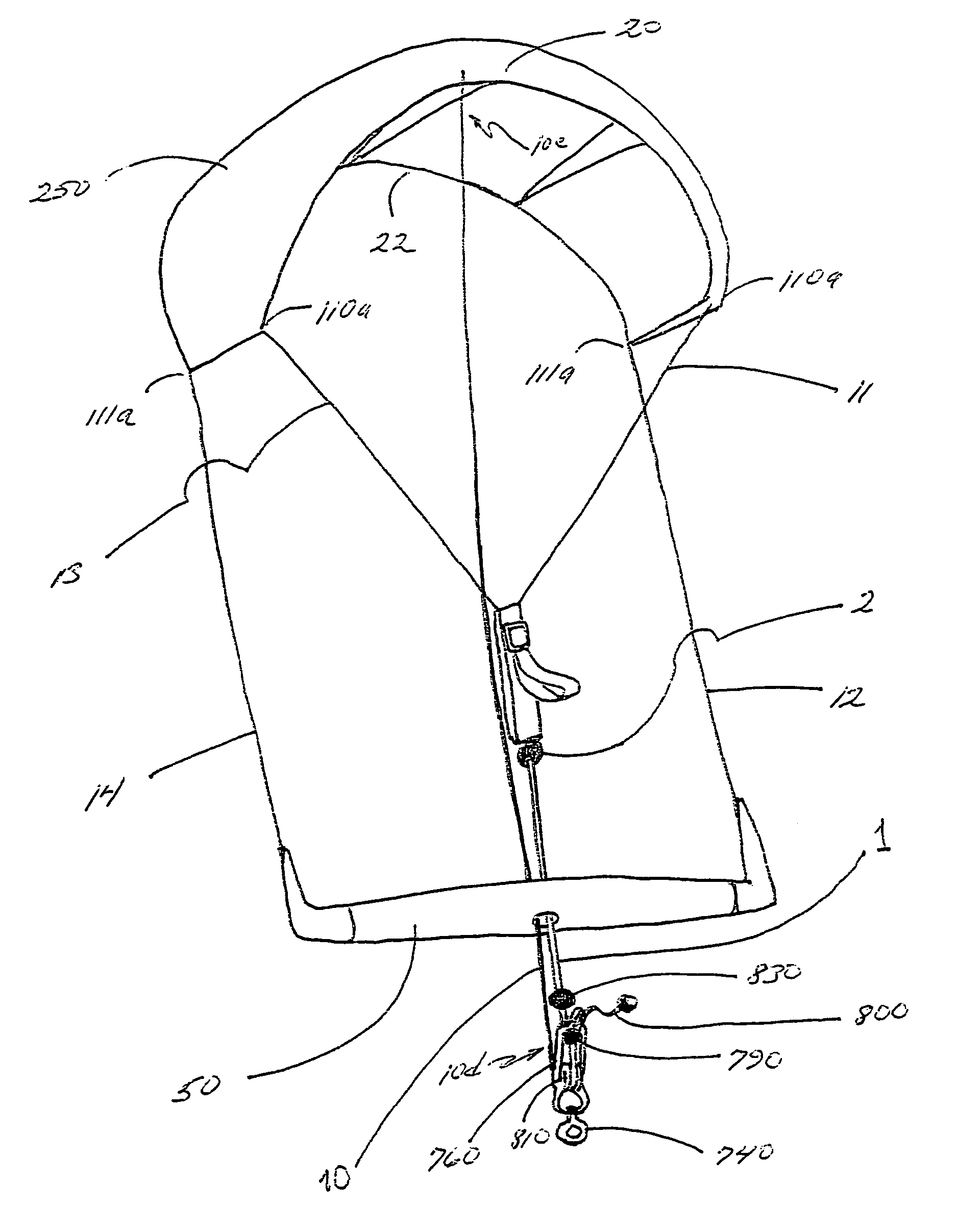
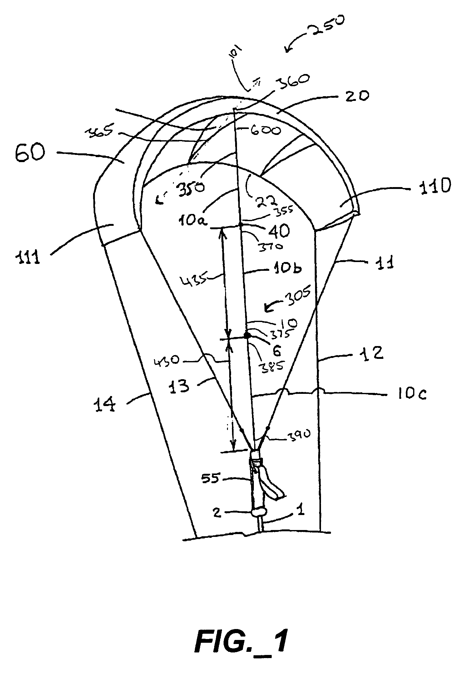
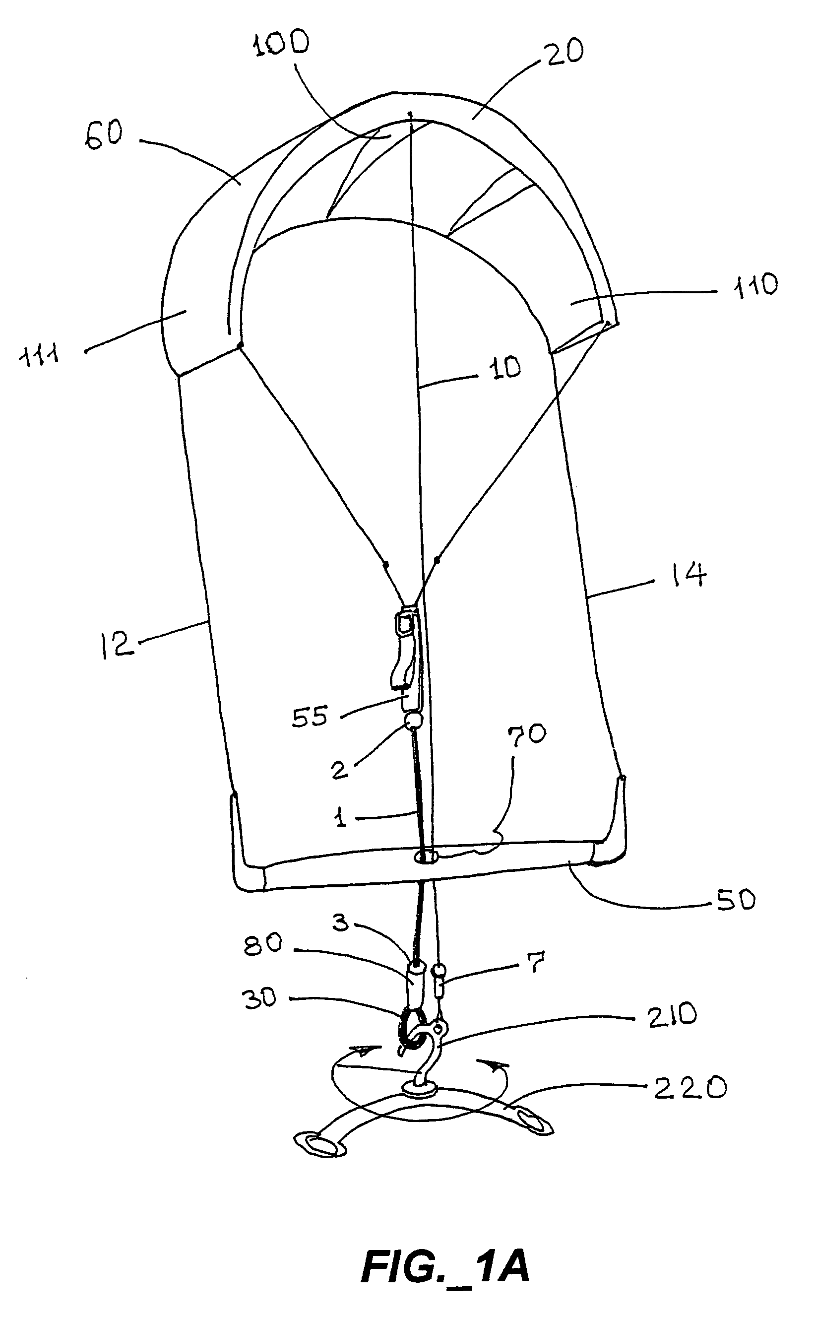
[0217]FIGS. 1–16 illustrate a kite safety device 305 for a kite 250 that has an airfoil 60 with leading 20 and trailing 22 edges, with at least two control lines, e.g., first control line 11, second control line 12, third control line 13, and fourth control line 14, attached to distal ends 110, 111 of the airfoil 60 and a control flying bar 50 attached to at least two of the control lines 11, 12, 13, 14. The safety device 305 has a trim line 1. The trim line 1 has an upper end 310 and a lower end 315 and central passageway 320 (FIG. 10) extending from the upper end 310 to the lower end 315 and is sized and shaped to fit slidably through a central opening (trim line guide hole) 70 in the control flying bar 50 of a kite.

[0218]The trim line 1 has a first stopper 2 adjacent the upper end 310 and a second stopper 130 adjacent the lower end. The stoppers 2, 130 are sized and shaped to prevent the upper 310 and lower 315 ends of the trim line 1 from passing through the central opening 70.

[...


PUM


Abstract

A kite safety, control, and depowering device for a kite having an airfoil with leading and trailing edges, at least two control lines attached to the airfoil and a control flying bar attached to at least two of the control lines. The device features a continuous trim and safety flying line disposed at their lower ends over a rapid depowering apparatus. The depowering apparatus includes means for capturing and rapidly releasing an expansion disposed on the trim line, such that when rapid depowering is required, a simply release mechanism may be actuated to change the angle of attack of the airfoil rapidly.

Description

CROSS REFERENCE TO RELATED APPLICATIONS[0001]The present application is a continuation-in-part of U.S. Utility patent application Ser. No. 10 / 613,133, filed Jul. 3, 2003, pending, which claims priority from U.S. Provisional Patent Application Ser. No. 60 / 394,364, filed Jul. 3, 2002.STATEMENT REGARDING FEDERALLY SPONSORED RESEARCH OR DEVELOPMENT[0002]Not applicable.REFERENCE TO A MICROFICHE APPENDIX[0003]Not applicable.TECHNICAL FIELD[0004]The invention pertains to equipment used in the sport of kite surfing and related activities involving kites having controllable airfoils. More particularly, the invention relates to a kite safety, control, and rapid depowering apparatus which selectively manages the control lines associated with such a kite, enabling the user to tightly and quickly adjust the angle of attack of the kite and to rapidly depower the kite to brake rapidly.BACKGROUND INFORMATION AND DISCUSSION OF RELATED ART[0005]The present invention relates to multiple line kites. Al...

Claims


Application Information

Patent Timeline
Patent Type & Authority Patents(United States)
IPC IPC(8): B64C31/06
CPCB63B35/7979Y10S244/902B64C2031/065B63H8/16B63H8/58B63H8/18
Inventor POUCHKAREV, ALEXANDER S.
Owner POUCHKAREV ALEXANDER S
Why Eureka
Try Eureka