Optical part, optical module sleeve, optical receiving module, optical communication module, and method of making optical part

Active Publication Date: 2006-05-02
SUMITOMO ELECTRIC IND LTD
View PDF13 Cites 13 Cited by
  • Summary
  • Abstract
  • Description
  • Claims
  • Application Information

AI Technical Summary

Benefits of technology

[0006]However, such a short ferrule has its length of about 3 to 4 mm at the minimum to contain the internal optical fiber therein. This length expands the size of the optical receiving module. Since the short ferrule used therein is costly, the optical receiving module tends to be expensive.
[0007]Therefore, it is an object of the present invention to provide an optical part, a receiving module sleeve, an optical receiving module, and an optical communication module which are small in size and excellent in transmission quality, and a method of making the optical part.
[0014]In one configuration of the optical receiving module, the sleeve comprises an optical part. The optical subassembly is attached to the second portion of the sleeve and is optically coupled with the optical part. The optical subassembly comprises an optical device and an optical lens, and the optical lens is optically coupled with the optical device. The optical device includes a semiconductor light-receiving element. In the optical receiving module, the optical part is useful for reducing the reflection of light from the optical fiber. Since the optical part is installed in the sleeve, positioning the optical part to the sleeve is not needed.
[0015]In another configuration of the optical receiving module, the optical subassembly is attached to the second portion of the sleeve so as to be optically coupled with the other of the pair of faces of the third portion of the sleeve. The optical subassembly comprises an optical device and an optical lens, and the optical lens is optically coupled with the optical device. The optical device includes a semiconductor light-receiving element. The sleeve does not comprise the optical part, whereas the light-transmitting portion is integrally formed with the sleeve. Therefore, positioning the optical part to the sleeve is unnecessary. The longitudinal length of the optical communication module is reduced. In the optical receiving module, the other of the pair of faces of the third portion in the sleeve is used for reducing the reflection of light from the optical fiber.

Problems solved by technology

Since the short ferrule used therein is costly, the optical receiving module tends to be expensive.
Therefore, positioning the optical part to the sleeve is unnecessary.

Method used


Image

  • Optical part, optical module sleeve, optical receiving module, optical communication module, and method of making optical part
  • Optical part, optical module sleeve, optical receiving module, optical communication module, and method of making optical part
  • Optical part, optical module sleeve, optical receiving module, optical communication module, and method of making optical part

Examples


first embodiment

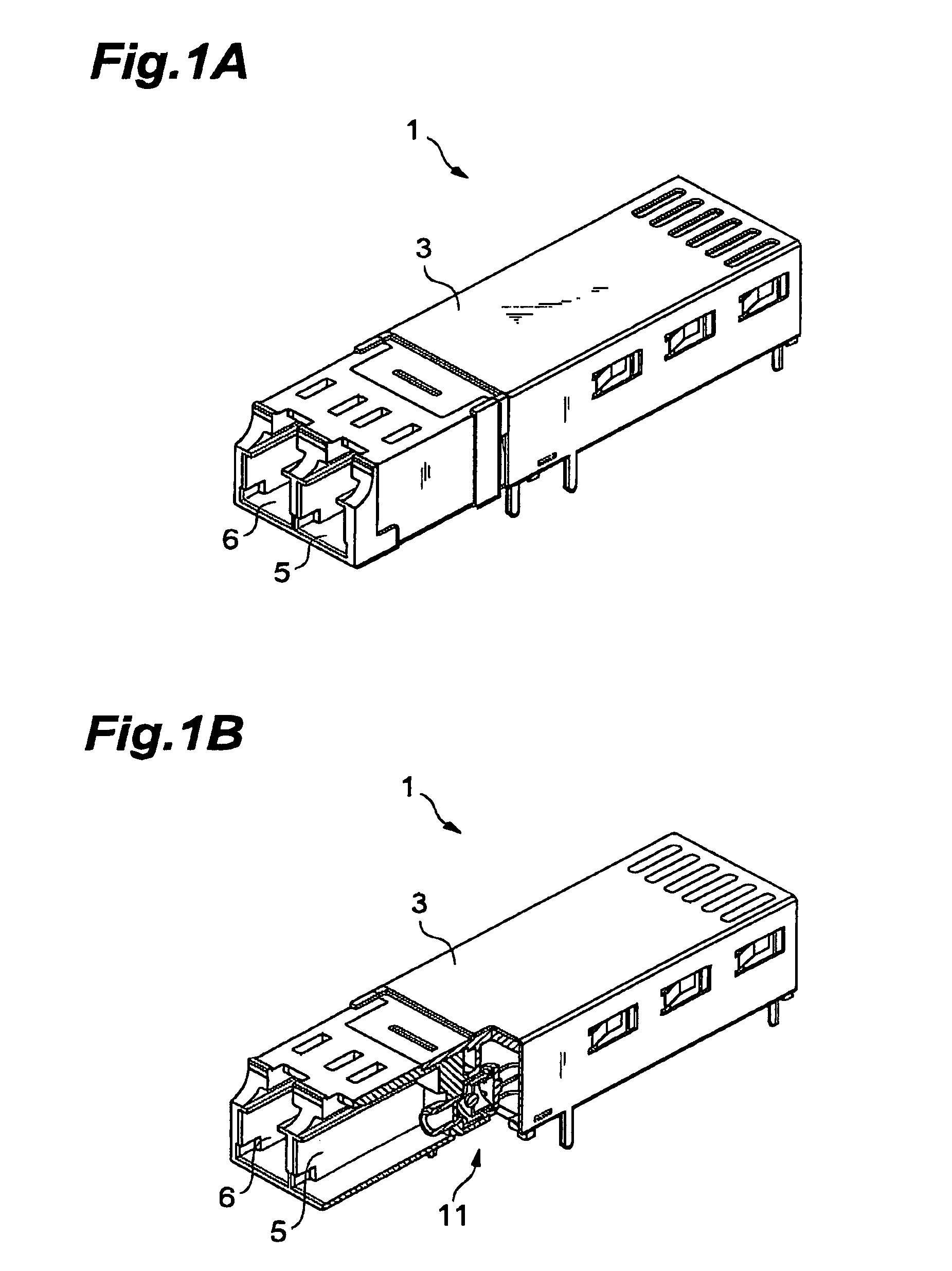
[0046]FIG. 1A is a perspective view showing an optical communication module mounted with the optical receiving module in accordance with one embodiment. FIG. 1B is a partly cutaway view of the optical communication module shown in FIG. 1A. This optical communication module (transceiver) 1 is an apparatus for converting electric signals into optical signals and vice versa.

[0047]The optical communication module 1 comprises an optical receiver 11 for receiving optical signals and converting them into electric signals, and a transmitter for converting electric signals into optical signals and transmitting thus generated optical signals. The optical transmitter is connected to a first receptacle 6 for accommodating a transmitting optical connector, whereas the optical receiver 11 is connected to a second receptacle 5 for accommodating a receiving optical connector. FIG. 1B shows the arrangement of the receiver 11 and second receptacle 5, whereas the optical transmitter and first receptac...

second embodiment

[0089]FIGS. 11A and 11B are perspective views showing the optical part in accordance with another embodiment. FIG. 11A shows one face of the optical part 90, whereas FIG. 11B shows the other face of the optical part 90. FIG. 12A shows a face 92b of the optical part 90. FIG. 12B shows a face 92a of the optical part 90. FIG. 12C is a sectional view taken along the line V—V shown in FIG. 12AFIG. 12D is a side view showing the front face of a reference surface.

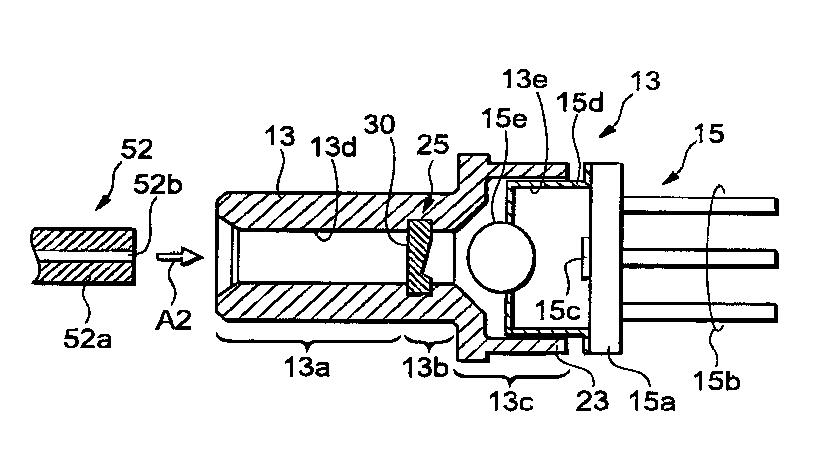
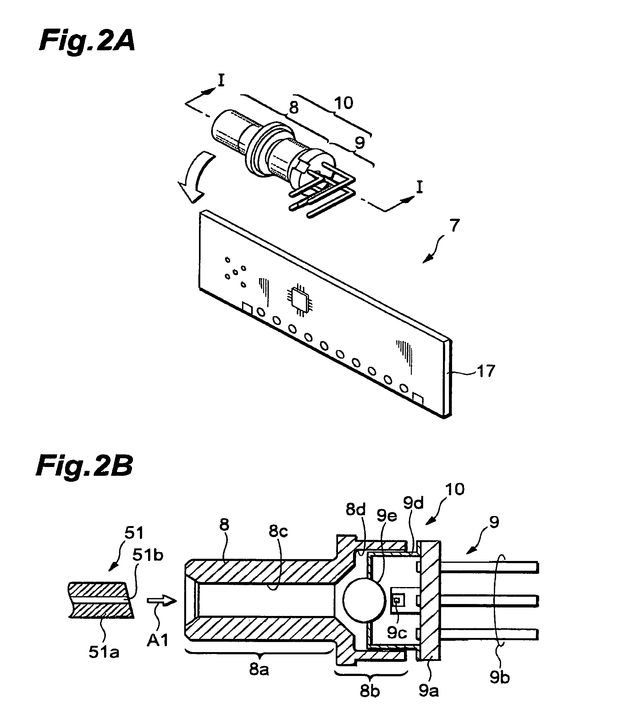
[0090]The optical part 90 will be explained in further details with reference to FIGS. 11A, 11B, and 12A to 12D. The optical part 90 is incorporated in a sleeve. In an optical module, this sleeve is used for optically coupling an optical device, such as a semiconductor light-receiving element or semiconductor light-emitting device (reference numeral 9c in FIG. 2B or reference numeral 15c in FIG. 3B), to an optical fiber. The optical part 90 comprises a light-transmitting portion 92 and a supporting portion 94. The optical part 90 ...

third embodiment

[0121]FIGS. 16A and 16B are views showing forming dies for molding an optical part FIG. 16A shows one die 112 of a pair of forming dies for molding the optical part, whereas FIG. 16B shows the other die 114. The forming die 112 comprises a cavity 112a for forming the light-transmitting portion 92 and supporting portion 94 of the optical part 90, a cavity 112b for forming the protrusion 9, a face 112c for forming the reference surface 98, and positioning parts 112d for positioning the forming dies 112 and 114 to each other. The cavity 112a comprises a projection 112e for forming one face 92a of the light-transmitting portion 92, and a side face 112f for forming the side faces 94a and 94b of the supporting portion 94. The forming die 114 comprises a cavity 114a for forming the light-transmitting portion 92 and supporting portion 94 of the optical part 90, a cavity 114b for forming the protrusion 96, a face 114c for forming the reference surface 98, and positioning parts 114d for posit...


PUM


Abstract

An optical part 25, which is used to be placed at an end face of an optical fiber, is constituted by a single light-transmitting material transparent to light transmitted through the optical fiber, and comprises an optical fiber contacting face 30 disposed in contact with the end face of the optical fiber, and an light emitting face 33 tilted with respect to a cross section perpendicular to the axis of the optical fiber. Since the light emitting face 33 is formed with an inclination, such an optical part 25 restrains reflected light occurring at the optical fiber end face from going back to the optical fiber. Also, since the optical part 25 is constituted by a single light-transmitting material, its configuration is simple, and the length can be shortened in the optical axis direction.

Description

CROSS-REFERENCE TO RELATED APPLICATIONS[0001]This application claims the benefit of the claiming priority of U.S. Provisional application Ser. No. 60 / 295,015, filed on Jun. 4, 2001, which provisional application is incorporated by reference herein.BACKGROUND OF THE INVENTION[0002]1. Field of the Invention[0003]The present invention relates to an optical communication module, an optical receiving module, a sleeve, an optical part, and a method of making the optical part.[0004]2. Description of the Related Art[0005]European Patent Publication No 826998-A2 discloses an optical receiving module in which a short ferrule is incorporated, whereas the short ferrule has an internal optical fiber therein. The optical receiving module is optically coupled to an output end of an optical fiber, whereas this end abuts against the input end of the internal optical fiber in the short ferrule. Light is emitted from the optical fiber, and this light is incident on the internal optical fiber contained...

Claims


Application Information

Patent Timeline
IPC IPC(8): G02B6/36G02B6/42
CPCG02B6/4207G02B6/4206
Inventor TONAI, ICHIROSATO, SHUNSUKE
Owner SUMITOMO ELECTRIC IND LTD
Why Eureka
Try Eureka