Shrinkage compensator for building tiedowns

a technology for building tiedowns and compensators, which is applied to washers, screws, threaded fasteners, etc., can solve the problems of unsatisfactory solution for wood loss, shrinkage, and building settle, and current tiedown systems (including rods, straps, etc.) do not provide a solution for this problem, and achieve the effect of preventing unintentional disassembly of the uni

Inactive Publication Date: 2006-05-02
COMMINS ALFRED
View PDF27 Cites 13 Cited by
  • Summary
  • Abstract
  • Description
  • Claims
  • Application Information

AI Technical Summary

Benefits of technology

[0013]In accordance with the above-identified needs, it is an objective to provide a self-powered take-up system for removing slack from between shearwalls and their anchors. It is an objective to provide a high reliability with a 30 year minimum life expectancy. It is desired that the apparatus be a non-reversing (locking in the extended position) design that may be shipped in a cocked, or preloaded position, ready to fire or deploy to extend in height, and having a trigger mechanism to actuate operation thereof. It is desirable to provide a simple mechanism that may be activated in the field with a minimum of skill and tools. In certain embodiments it is desirable to provide smooth and continuous motion of the take-up process, involving no stepped functions. Nevertheless, in other embodiments, step functions may be desirable. It is desired to minimize backlash to within thousandths of an inch.
[0014]It is desired to provide an apparatus that may be concentrically loaded, and thus able to tolerate and better center eccentric loads. In practice, few items are ever installed fully squared, and the take-up apparatus in accordance with the invention is preferably able to function at loads equal to the full tiedown design load for any anchor to which the take-up is attached. Ultimately, the tiedown should withstand the full ultimate load of a corresponding tiedown apparatus without jamming or deflecting substantially (e.g. more than one sixteenth of an inch).
[0020]A take-up unit according to the present invention may also include a safety mechanism which may be provided by an interference between structure carried by the sliding and base members. The safety mechanism may be engaged, or enabled, during manufacture of the take-up unit subsequent to preloading one or more springs. One function of a safety mechanism is to prevent unintentional disassembly of the unit. A safety mechanism may determine a maximum range of relative motion between base and sliding members. An exemplary safety mechanism is formed by a flange carried by the sliding member, the flange being deformed into position to interfere with structure carried by the base member subsequent to assembly of the unit. The interference created between the flange and base member structure prevents unintentional disassembly of the unit thereafter. A snap ring may also be employed to perform the same function as the flange.
[0022]A take-up unit may be fashioned to have a sliding member that includes a right-hand threaded hole for engagement with a commercial anchor bolt. The sliding member typically includes a bearing surface against which to receive a jam nut, the jam nut also being in engagement with the anchor bolt. To further prevent inadvertent rotation of the sliding member about the anchor bolt under the action of a preloaded spring, a thread having a different direction than the anchor bolt thread is preferably provided between the base and sliding members. To accommodate commercially available right hand threaded anchor bolts, a left-hand threaded engagement may preferably be provided as a slidable capture interface between sliding and base elements.

Problems solved by technology

Over time, ranging from several months to several years, wood loses moisture, shrinks, and the building settles.
Current tiedown systems (including rods, straps, and the like) do not provide a solution for this problem.
Substantial building damage can result before the anchoring hardware is loaded (in tension).
Hardware that does not immediately engage the base of an anchored wall can result in a 50 percent to 70 percent loss in lateral, load-bearing capacity.
The problem arises, typically, in wind storms of great power, or in earthquake conditions.
A building under such circumstances may be violently loaded or shaken back and forth in a lateral direction with respect to the extent of the wall.
Gaps caused by wood shrinkage may further introduce an undesirable shock load to the anchoring system as the gaps are closed and the anchor system is finally loaded.
However, the as-built building is generally not the building that will be sustaining loads induced by earthquake shaking or by wind.
Moreover, under load, wood crushes or collapses in compression under the loading of a wall.
Neither shrinkage nor crushing are well-accommodated or otherwise resolved in currently available systems.
These problems lead to a significant reduction in the lateral, load-bearing capacity of shearwalls.

Method used


Image

  • Shrinkage compensator for building tiedowns
  • Shrinkage compensator for building tiedowns
  • Shrinkage compensator for building tiedowns

Examples


Embodiment Construction

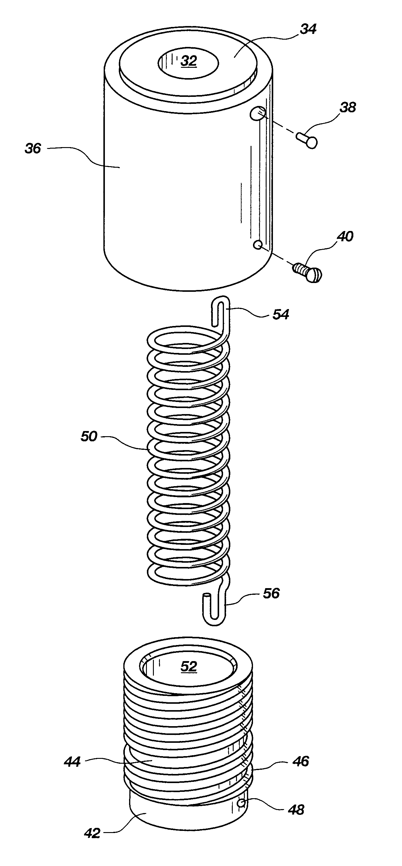
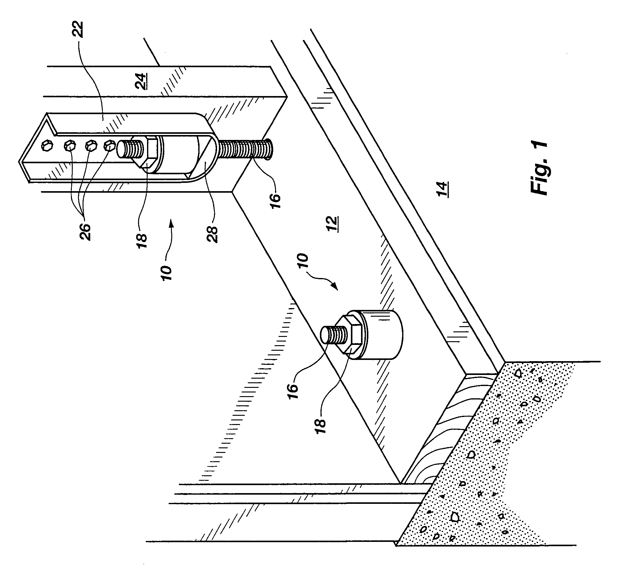
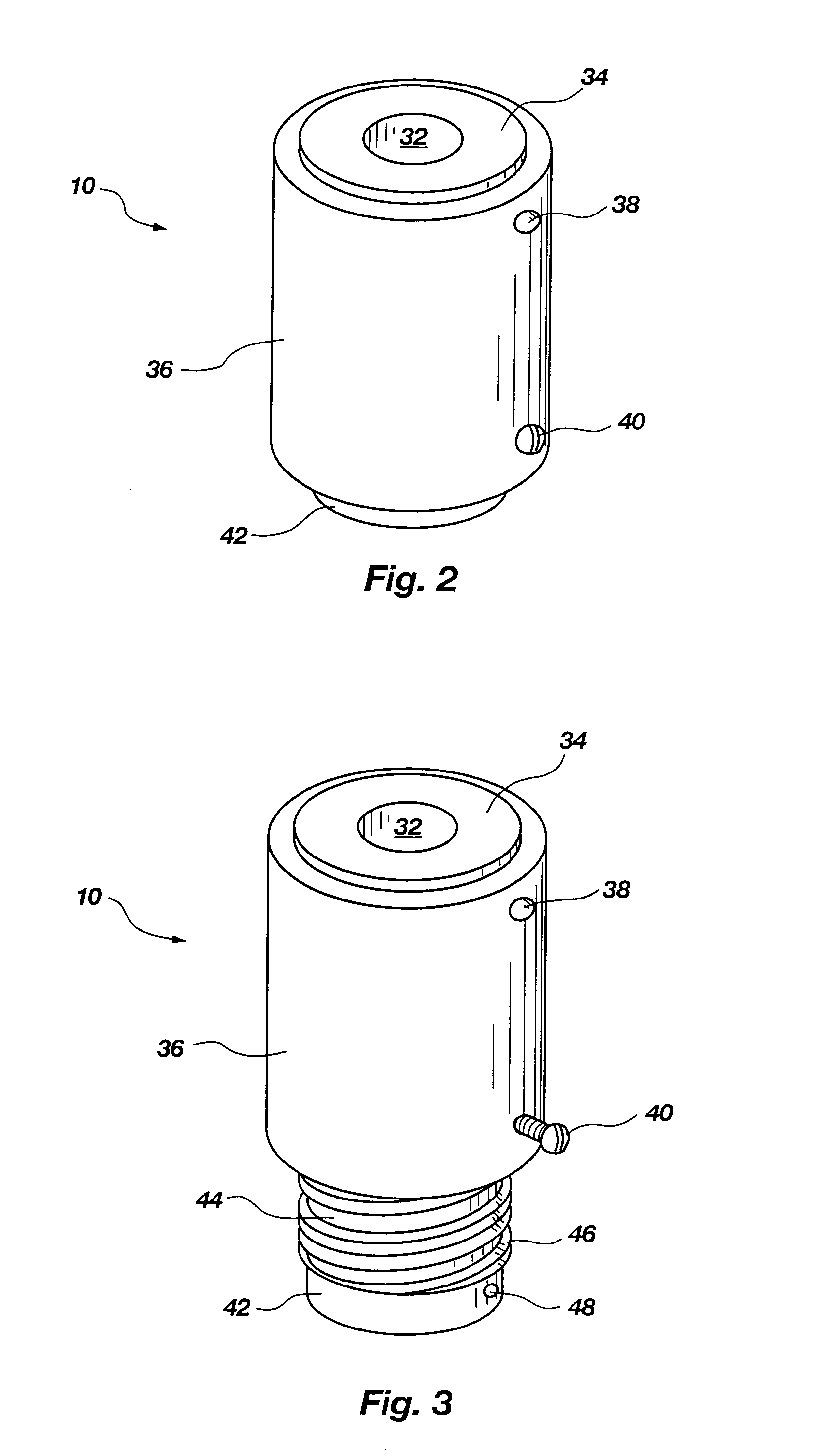
[0033]It will be readily understood that the components of the present invention, as generally described and illustrated in the Figures herein, could be arranged and designed in a wide variety of different configurations. Thus, the following more detailed description of the embodiments of the system and method of the present invention, as represented in 1 through 8B, is not intended to limit the scope of the invention. The scope of the invention is as broad as claimed herein. The illustrations are merely representative of certain, presently preferred embodiments of the invention. Those presently preferred embodiments of the invention will be best understood by reference to the drawings, wherein like parts are designated by like numerals throughout.

[0034]Those of ordinary skill in the art will, of course, appreciate that various modifications to the details of the Figures may easily be made without departing from the essential characteristics of the invention. Thus, the following des...


PUM


Abstract

An automatic, self-energized, length extending, take-up unit for general use in wall hold down systems. The take-up unit is generally installed as a separate element, independent of threaded retaining elements of a hold down system. One embodiment includes an internal, preloaded, coil spring to rotate a threaded sliding member relative to a threaded base member, thereby to extend a height of the take-up unit. A trigger mechanism may be included to prevent unintended actuation of the unit. Additionally, a safety mechanism may be included to prevent inadvertent separation of a base member and a sliding member, thereby to prevent loss of a preload in an energizing spring.

Description

RELATED APPLICATIONS[0001]This application is a continuation of U.S. patent application Ser. No. 10 / 146,531 filed on May 15, 2002 and now U.S. Pat. No. 6,585,469 entitled SHRINKAGE COMPENSATOR FOR BUILDING TIEDOWNS.BACKGROUND[0002]1. The Field of the Invention[0003]This invention pertains to building construction, and, more particularly, to novel methods and apparatus for anchoring building walls to foundations and lower floors thereof. The invention provides an automatic adjusting mechanism to remove slack in a hold down system caused by wood shrinkage over time or wood crushing caused by earthquakes.[0004]2. The Background Art[0005]Wood products change dimensions as moisture content changes. Floor systems using solid sawn joists typically shrink approximately five percent in dimensions across the grain. Under certain conditions they have been known to shrink six and one-half percent within a year. This shrinkage is typically part of the overall process and condition called “settli...

Claims


Application Information

Patent Timeline
Patent Type & Authority Patents(United States)
IPC IPC(8): F16B43/00E02D27/00E04B1/00E04B1/41E04B1/58F16B5/02F16B35/04F16B39/24
CPCF16B43/009F16B5/0241F16B5/0233E04B2001/2688
Inventor COMMINS, ALFRED
Owner COMMINS ALFRED
Why Eureka
Try Eureka