Front access lan and timing (SATT)

a technology of front access lan and connector, which is applied in the direction of electrical apparatus construction details, coupling device connections, instruments, etc., can solve the problems of difficulty in cleaning and servicing optical fibers, difficulty in traversing shelf-to-shelf separation, and difficulty in approving and approving. , to achieve the effect of facilitating access and enhancing security of access covers

Active Publication Date: 2006-05-02
CIENA
View PDF7 Cites 9 Cited by
  • Summary
  • Abstract
  • Description
  • Claims
  • Application Information

AI Technical Summary

Benefits of technology

[0011]Conveniently the faceplate assembly may be provided with a plurality of retention tabs on said side edges disposed adjacent to the aperture end of the cabling volume for retaining cables therewithin. These retention tabs assist in maintaining cables within the cabling volume.
[0012]Conveniently the faceplate assembly may be provided with a detachable access cover securable to the elongated housing for providing a vertical front face to the cabling volume. This access cover provides the advantages of further assisting in retaining cables within the cabling volume, precluding accidental ingress to the cabling volume, and covering the plurality of cables terminating on the plurality of connectors thereby resulting in a more pleasing appearance.
[0013]Also conveniently, the access cover may be provided with a hinge and also with a locking means. The provision of a hinge allows for all the advantages of an access cover while eliminating the necessity of storing the access cover when working with the cables and connectors. The provision of a locking means enhances security of the access cover, both against accidental opening and providing a measure of protection against unauthorized intrusion.
[0014]Advantageously, the second side surface may have a panel and a vertical hinge means whereby the panel may be displaced away from the first side surface upon withdrawing the circuit pack from the equipment shelf. As a further advantage, the circuit board upon which the faceplate assembly is disposed may have a bridging cable connected at a first end to the circuit pack and a backplane connector connected at a second end of the bridging cable for connection to a backplane or a midplane of the equipment shelf. The bridging cable allows the circuit board and faceplate assembly to be partially withdrawn from the equipment shelf, allowing the panel to be opened widely. This effectively opens up the cabling volume for facilitating access to the plurality of connectors disposed on said rear surface. Further, the widened access facilitates access to and rearrangement of the cables within the cabling volume in the event that a particular specific cable needs to be separated and removed or replaced.
[0019]Advantages of these features of the method include better retention of cables within the cabling volume, a means for precluding accidental ingress to the cabling volume, and a more pleasing appearance when the access cover conceals a plurality of cables. Further advantages of several of the features include enhanced access to the cabling volume and enhanced security of the cabling volume and cable terminations.

Problems solved by technology

This approach runs into difficulties when fiber optic signalling paths are required between circuit boards, and when inter-shelf signalling i.e. signalling paths between cards on different shelves are required.
With optical connectors at the back of the shelf, cleaning and servicing of the optical fibers is difficult because of limited accessibility.
Signalling paths between cards on different shelves encounters the difficulty of traversing the shelf-to-shelf separation as there is no backplane or midplane.
Provision of faceplate connectors carries with it the problems of exposure to mechanical damage, and a problem of aesthetics.
The resulting placement tends to leave a portion of the cable exposed to accidental and incidental mechanical damage.
Further, a plurality of cables terminating upon circuit card faceplates may begin to resemble a tangled skein, detracting from the aesthetics of the equipment installation and resulting in an unfinished or unprofessional impression of the equipment.

Method used


Image

  • Front access lan and timing (SATT)
  • Front access lan and timing (SATT)
  • Front access lan and timing (SATT)

Examples


Embodiment Construction

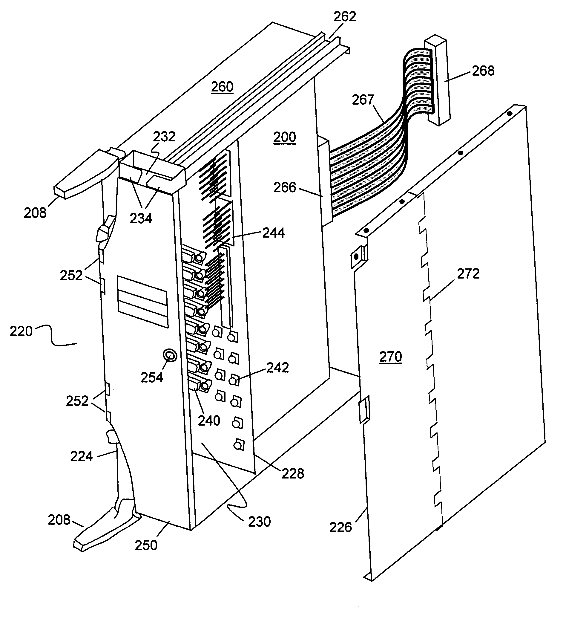
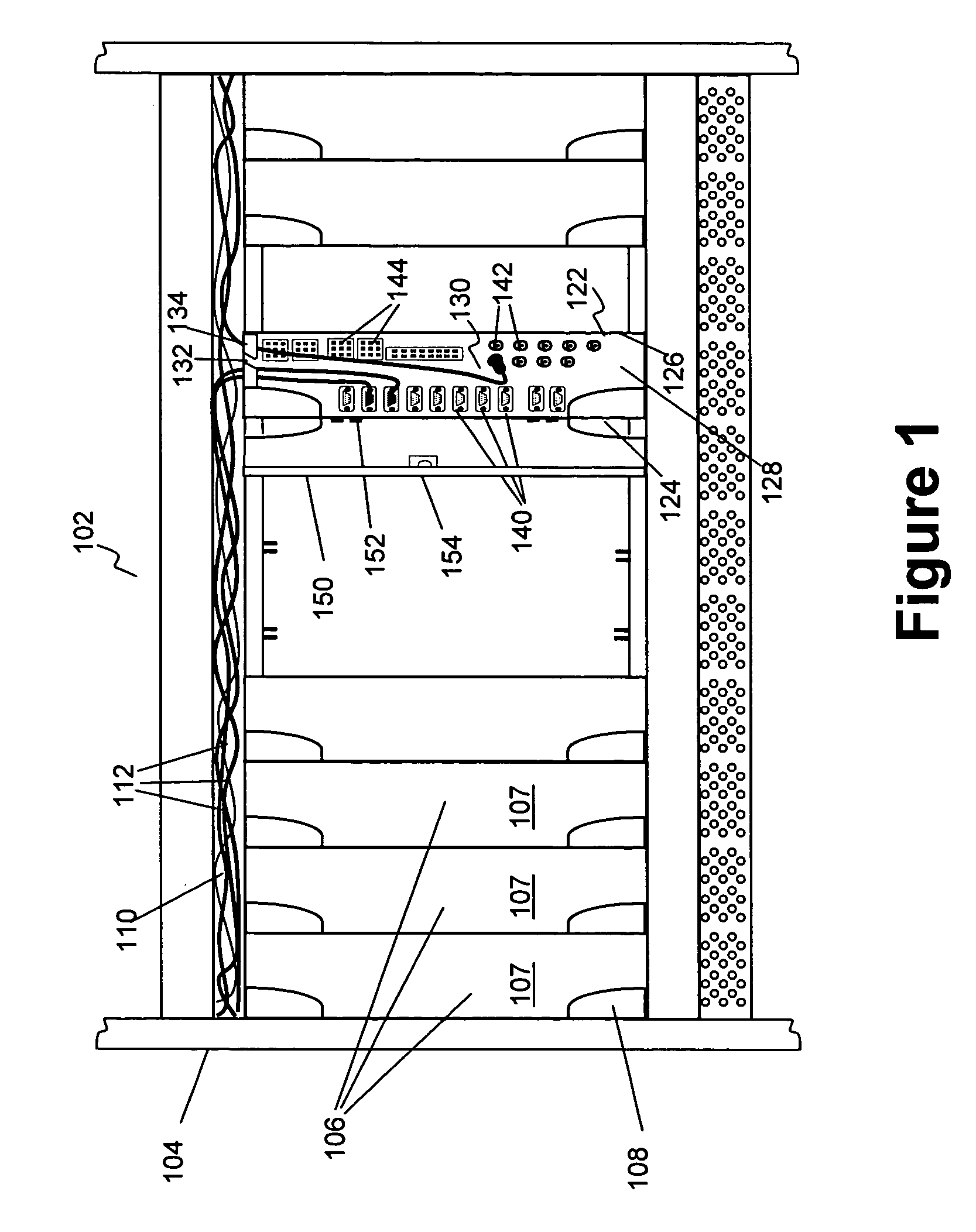
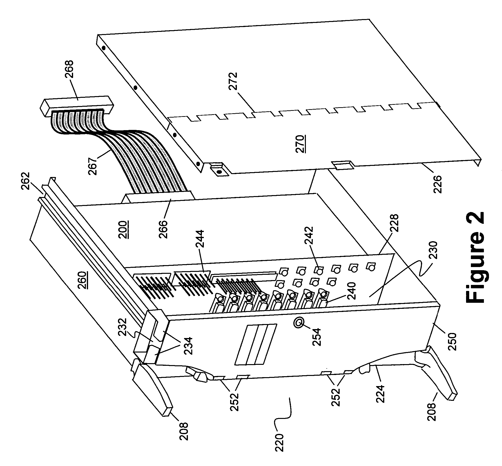
[0025]Referring to FIG. 1 there may be seen a shelf 102 for electronic equipment mounted in typical style on the frame 104 of a rack. Within the shelf are mounted circuit cards 106 adjacent to one another across the shelf and oriented vertically. Alternative arrangements may also provide for horizontal mounting (not shown). The circuit cards 106 have connectors at the rearmost edge which are mated to corresponding connectors located on the backplane or midplane of the shelf. The circuit cards have faceplates 107 at the foremost edge. These faceplates 107 serve a variety of purposes including providing mechanical stiffening, providing a protective front enclosure face for the printed circuit board assembly, providing a means for EMC / RFI shielding, providing a background for labelling purposes, and acting as a mounting point for display elements and switches. On the circuit cards may be seen card ejectors 108 which serve to mechanically assist in both seating the connectors, securing ...


PUM


Abstract

A recessed connectorized faceplate assembly for connecting multiple cables at the front of an electronics equipment shelf. The recessed connectorized faceplate assembly includes a connectorized faceplate defining the back wall of a cabling volume behind where a standard faceplate would normally be situated. The cabling volume has an aperture admitting cables routed from a cable trough situated between equipment shelves. The front of the cabling volume comprises a hinged faceplate granting access to the cabling volume. Access is via a pivoting panel forming one of the sidewalls. A bridging cable connecting the circuit card containing the faceplate to the backplane allows partial withdrawal of the card while maintaining connections.

Description

FIELD OF THE INVENTION[0001]The present invention relates to a recessed connectorized faceplate assembly and is particularly concerned with accommodating a plurality of cable terminations with protection of cable connections.BACKGROUND OF THE INVENTION[0002]In existing electronic systems it is well known to use printed circuit board assemblies intended to be mounted in shelves. The printed circuit boards assemblies or cards are disposed next to each other in the shelf and are oriented vertically to facilitate cooling. These printed circuit board assemblies typically include a printed circuit board on which are mounted electronic and optical components. At the rearmost edge the printed circuit board electrical and optical connectors are disposed for connection to a backplane or midplane provided in the shelf. The printed circuit board assemblies also typically use a faceplate mounted to the printed circuit board on the foremost edge. These faceplates serve a variety of purposes inclu...

Claims


Application Information

Patent Timeline
Patent Type & Authority Patents(United States)
IPC IPC(8): H01R9/22H01R9/24H01R13/56H01R13/60H05K7/14
CPCH01R9/2416H05K7/1448H01R13/56
Inventor AZIZ, FARIDAJERSCH, PETERCOSMAN, LLOYD
Owner CIENA
Why Eureka
Try Eureka