
Insertion device for deformable intraocular lens

Active Publication Date: 2006-05-02
STAAR JAPAN
View PDF20 Cites 69 Cited by
  • Summary
  • Abstract
  • Description
  • Claims
  • Application Information

AI Technical Summary

Benefits of technology

[0023]One object of the present invention is to provide an insertion device for a deformable intraocular lens which can restrict rotation of an intraocular lens about a center axis of the insertion tube in order to stably maintain insertion direction and insertion speed of the intraocular lens.
[0024]Another object of the present invention is to provide an insertion device for a deformable intraocular lens which can frictionally limit advancement speed of an intraocular lens at the time of stress release in order to prevent damage of the lens and enable more reliable insertion of the lens into the eye.
[0025]According to the first aspect of the present invention, there is provided an insertion device for inserting a deformable intraocular lens into the eye, in which a guide for an intraocular lens is provided on the inner surface of the insertion tube in order to restrict rotation of an intraocular lens about a center axis of the insertion tube when the intraocular lens is passed through the insertion tube in a folded condition. Accordingly, stable insertion operation is enabled, and operation for implanting an intraocular lens can be performed by an operator who does not have a high degree of experience. Moreover, since the posture of the intraocular lens within the insertion tube is stable, the insertion speed of the intraocular lens can be controlled stably.
[0026]According to the second aspect of the present invention, there is provided an insertion device for inserting a deformable intraocular lens into the eye, in which the insertion tube has a stress release structure for releasing stresses of the lens produced during deformation of the lens, and a frictional-resistance increasing structure provided on an inner surface of the insertion tube and in the vicinity of the stress release structure. Therefore, the lens can be inserted into the eye at slower speed as compared with conventional intraocular-lens insertion devices having the stress release structure only. Thus, the intraocular lens can be inserted into the eye safely.

Problems solved by technology

As a result, the positional relation between the slit provided at the tip end of the insertion tube and the folded intraocular lens changes, thereby making it impossible for an operator to eject the intraocular lens from the tip end of the insertion tube in desired conditions.
Therefore, insertion direction and insertion speed of the intraocular lens are difficult to control with stability and high reproducibility, and therefore, operation of implanting an intraocular lens requires a high level of skill.
Therefore, in the case in which the frictional resistance between the lens and the insertion tube is small, stress generated during deformation are released at a time when the lens is ejected from the tip end of the insertion tube into the eye, so that the lens flies out into the eye, possibly damaging the tissue within the eye.
In this case, when the lens is inserted into the eye, the lens may come into contact with the tissue and damage it.

Method used


Image

  • Insertion device for deformable intraocular lens
  • Insertion device for deformable intraocular lens
  • Insertion device for deformable intraocular lens

Examples


Embodiment Construction

[0052]Embodiments of the present invention will be described with reference to the accompanying drawings.

[0053]First, an intraocular-lens insertion device according to a first embodiment of a first aspect of the present invention will be described.

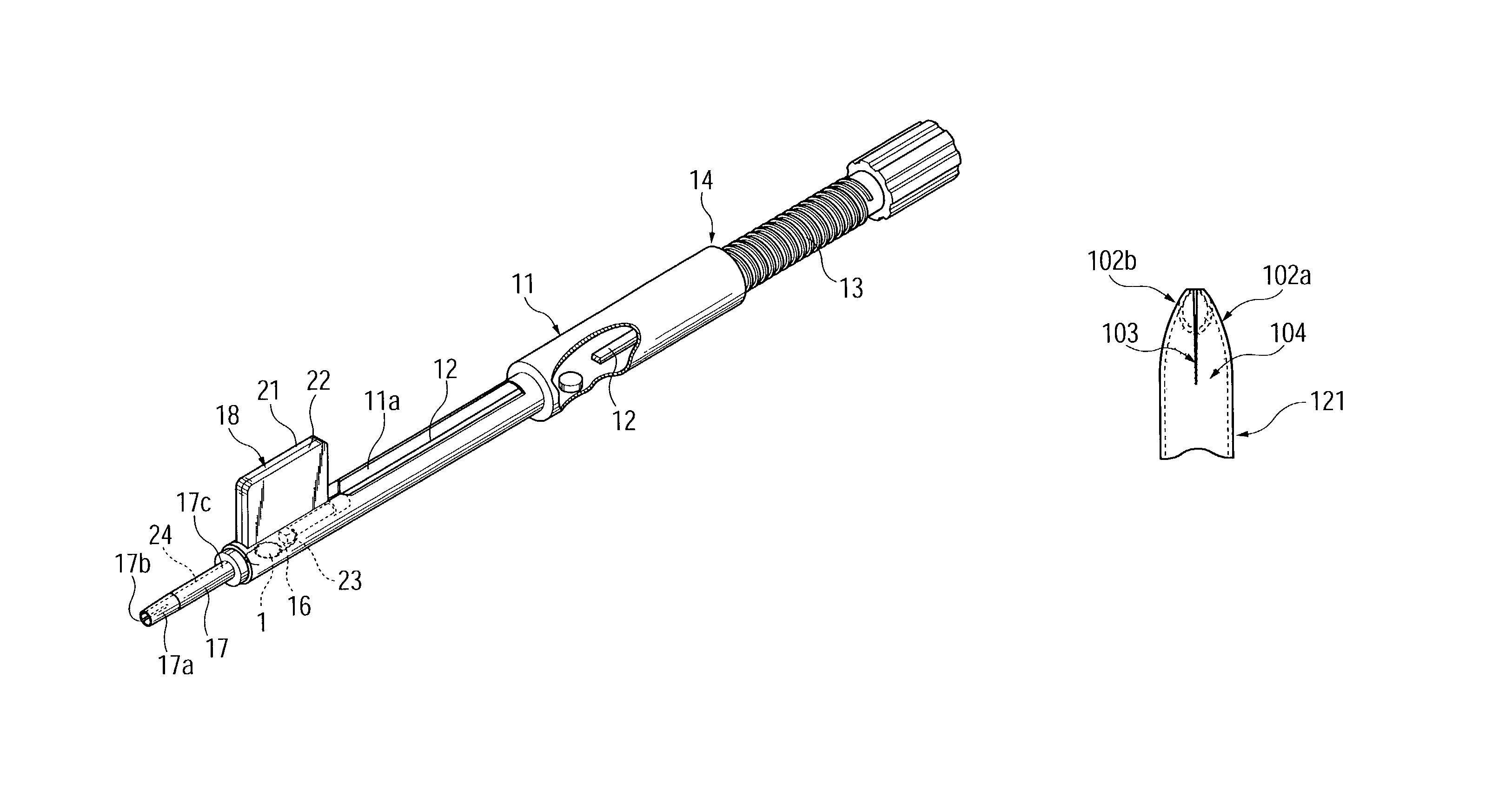
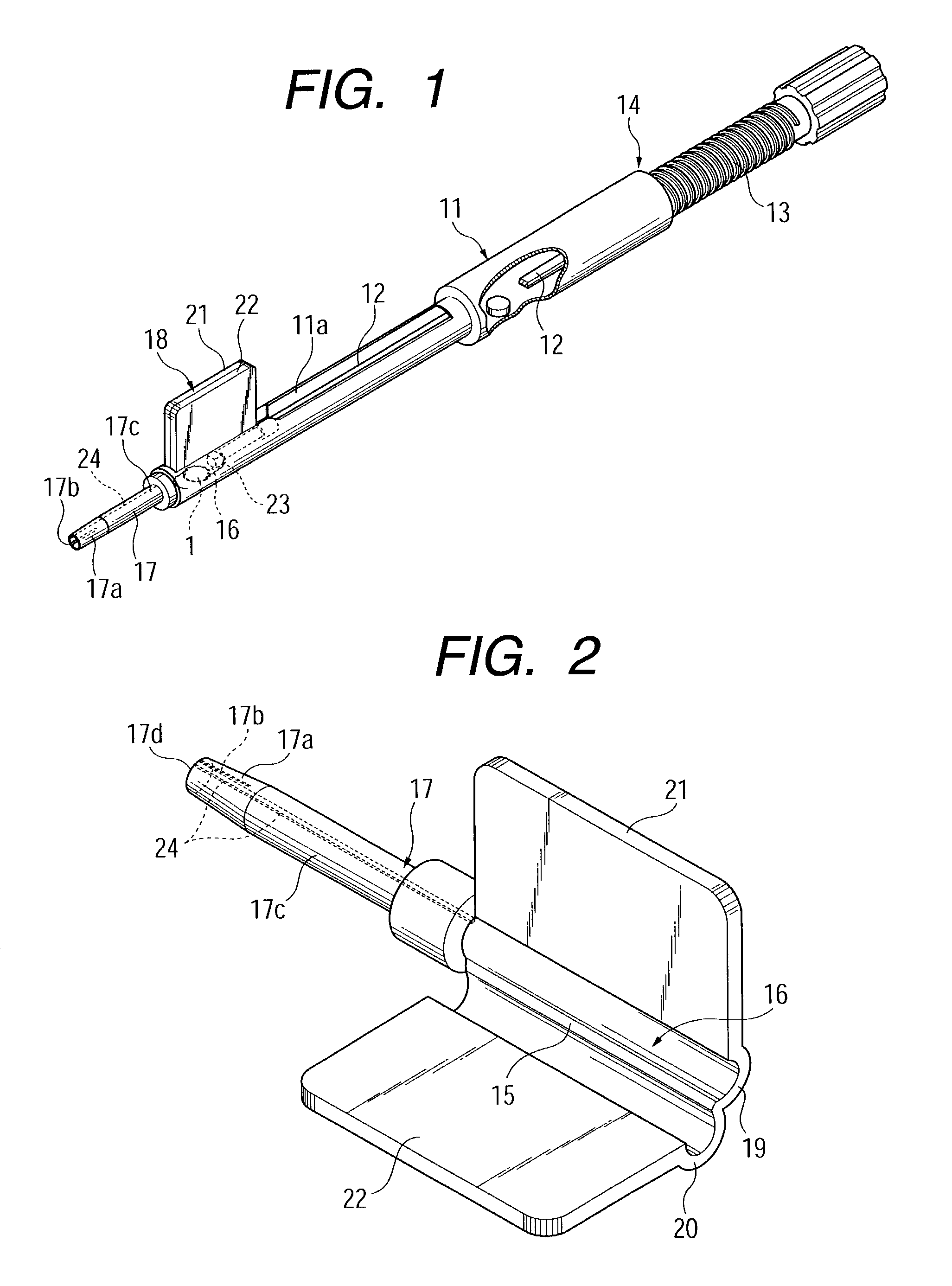
[0054]FIG. 1 is a perspective view of the intraocular-lens insertion device according to the first embodiment of the first aspect of the present invention.

[0055]The intraocular-lens insertion device includes a generally cylindrical, tubular device body 11; a push rod 12 fitted into the device body 11; a push-out mechanism 14 including a male-thread shaft 13 in screw-engagement with a female thread (not shown) formed on the inner circumferential surface of the device body 11; and an enclosing member 18, which has a lens receiving section 16 having a hinge portion 15, and an insertion tube 17 projecting forward from the lens receiving section 16. An attachment groove 11a is formed in an upper portion of a tip end portion of the device body 1...


PUM


Abstract

An intraocular-lens insertion device is adapted to deform a deformable intraocular lens into a smaller size and insert the intraocular lens into an eye via an insertion tube. An intraocular-lens guide is provided on the inner surface of the insertion tube. The guide may be a rail-shaped projection or a groove, which extends parallel to a direction along which the intraocular lens is pushed out. A stress release structure is provided on the insertion tube in order to release stress of the intraocular lens produced due to deformation thereof. Moreover, a frictional-resistance increasing structure is provided on the inner surface of the insertion tube to be located in the vicinity of the stress release structure. The frictional-resistance increasing structure increases frictional resistance between the inner surface of the insertion tube and the intraocular lens. The frictional-resistance increasing structure may be a roughened surface which completely or partially covers the inner surface of the insertion tube.

Description

BACKGROUND OF THE INVENTION[0001]1. Field of the Invention[0002]The present invention relates to an insertion device for inserting a deformable intraocular lens into the eye. Examples of such a deformable intraocular lens include a deformable intraocular lens that is inserted into the eye in place of the natural lens when the latter is physically extracted because of cataracts, and a vision correction lens that is inserted into the eye for the sole purpose of vision correction.[0003]2. Description of the Related Art[0004]Implantation of an intraocular lens for treating cataract has been widely performed since 1949, when Ridley implanted for the first time an artificial lens; i.e., an intraocular lens, into the human eye in place of an opaqued natural lens during cataract surgery.[0005]As disclosed in Japanese Patent Application Laid-Open (kokai) No. 58-146346, there have been invented improved intraocular lenses which can be inserted into the eye through a small incision formed in t...

Claims


Application Information

Patent Timeline
IPC IPC(8): A61B17/00A61F2/16
CPCA61F2/1678A61F2/167
Inventor KIKUCHI, TOSHIKAZUKOBAYASHI, KENICHIYOSHIDA, HIDENORISHIMURA, KOJI
Owner STAAR JAPAN
Learn More