Systems and methods for composite webs with structured discrete polymeric regions

a polymeric region and composite web technology, applied in the field of systems and methods for manufacturing composite webs, can solve the problems of reducing throughput, affecting the shape and size of the polymeric region, and attaching discrete pieces, so as to achieve substantial control over the shape and size of the polymeric region, and control the shape, spacing and volume of the discrete polymeric region

Inactive Publication Date: 2006-05-02
3M INNOVATIVE PROPERTIES CO
View PDF81 Cites 46 Cited by
  • Summary
  • Abstract
  • Description
  • Claims
  • Application Information

AI Technical Summary

Benefits of technology

[0011]One advantage of the systems and methods of the present invention is the ability to transfer one or more discrete polymeric regions onto a major surface of a substrate, where the thermoplastic material of the discrete polymeric region can be forced against the substrate by a transfer roll. If the substrate is porous, fibrous, etc., pressure may enhance attachment of the discrete polymeric regions to the substrates by forcing a portion of the thermoplastic composition to infiltrate the substrate and / or encapsulate fibers of the substrate.
[0012]Another advantage of the systems and methods of the present invention is the ability to produce a composite web including discrete structured polymeric regions formed thereon in a single pass, with the input of a substrate and molten thermoplastic composition.
[0014]Another advantage of the systems and methods of the present invention is the ability to provide one or more discrete polymeric regions that extend for the length of the substrate (while not being formed over the width of the substrate, i.e., the discrete polymeric regions are not coextensive with the major surface of the substrate). The use a transfer roll to form such continuous discrete polymeric regions may advantageously provide substantial control over the shape and size of the polymeric regions.
[0015]Another advantage of the systems and methods of the present invention is the ability to provide different thermoplastic compositions across the width of the substrate, such that some discrete polymeric regions may be formed of one thermoplastic composition, while other discrete polymeric regions are formed of a different thermoplastic composition.
[0016]Still another advantage of the systems and methods of the present invention is that the types of features formed in different discrete polymeric regions on the substrate may vary both across the width of the composite web, as well as in the down-web direction.
[0017]Yet another advantage of the systems and methods of the present invention is the ability to provide one or more discrete polymeric regions on both major surfaces of a substrate. The discrete polymeric regions on the opposing major surfaces may be formed with the same or different features as desired.

Problems solved by technology

The handling and attachment of such discrete pieces can, however, be problematic, by potentially reducing throughput, causing waste (where the discrete pieces are not securely attached), etc.
The discrete pieces may also present relatively sharp edges that may be the source of irritation or discomfort.
For example, the use of extrusion dies and / or nozzles and any associated equipment (e.g., rotating blades, etc.) may result in limited shapes that can be formed on the webs.
Another potential disadvantage is that the speed at which the patterns may be formed is somewhat limited, especially where larger or thicker discrete polymeric regions are required.
Another disadvantage associated with extrusion-based systems is that the ability to form some shapes with any precision may be limited by the nature of the extrusion process.
As for the use of screen printing to form discrete polymeric regions, one disadvantage is that the amount of material that can be delivered through the orifices of a screen may not be sufficient to allow for forming of structures after deposition of the discrete polymeric regions, particularly when the thermoplastic compositions used for the discrete polymeric regions have a relatively high viscosity.
More importantly, however, may be the limitations on screen orifice size.
If the orifices are too large, the integrity of the screen can be impaired, particularly if higher pressures are required to force higher viscosity materials through the screen orifices.
Another disadvantage related to screen orifices is that orifices that extend continuously about the circumference of the screen printing roll cannot be provided without destroying the integrity of the roll.
Another disadvantage of screen printing processes is that the ability to force the molten thermoplastic composition into the substrate (where, e.g., the substrate is porous, fibrous, etc.) may be limited because no physical structure is provided directly opposite from the substrate on which the discrete polymeric regions are deposited.
Screen integrity may also limit the amount of pressure that can be applied to clean the screen of the molten thermoplastic composition between printing passes.
As the thermoplastic material builds up on the screen, it may be subject to charring or other degradation that could further hamper performance of the system as a whole.

Method used


Image

  • Systems and methods for composite webs with structured discrete polymeric regions
  • Systems and methods for composite webs with structured discrete polymeric regions
  • Systems and methods for composite webs with structured discrete polymeric regions

Examples


example 1

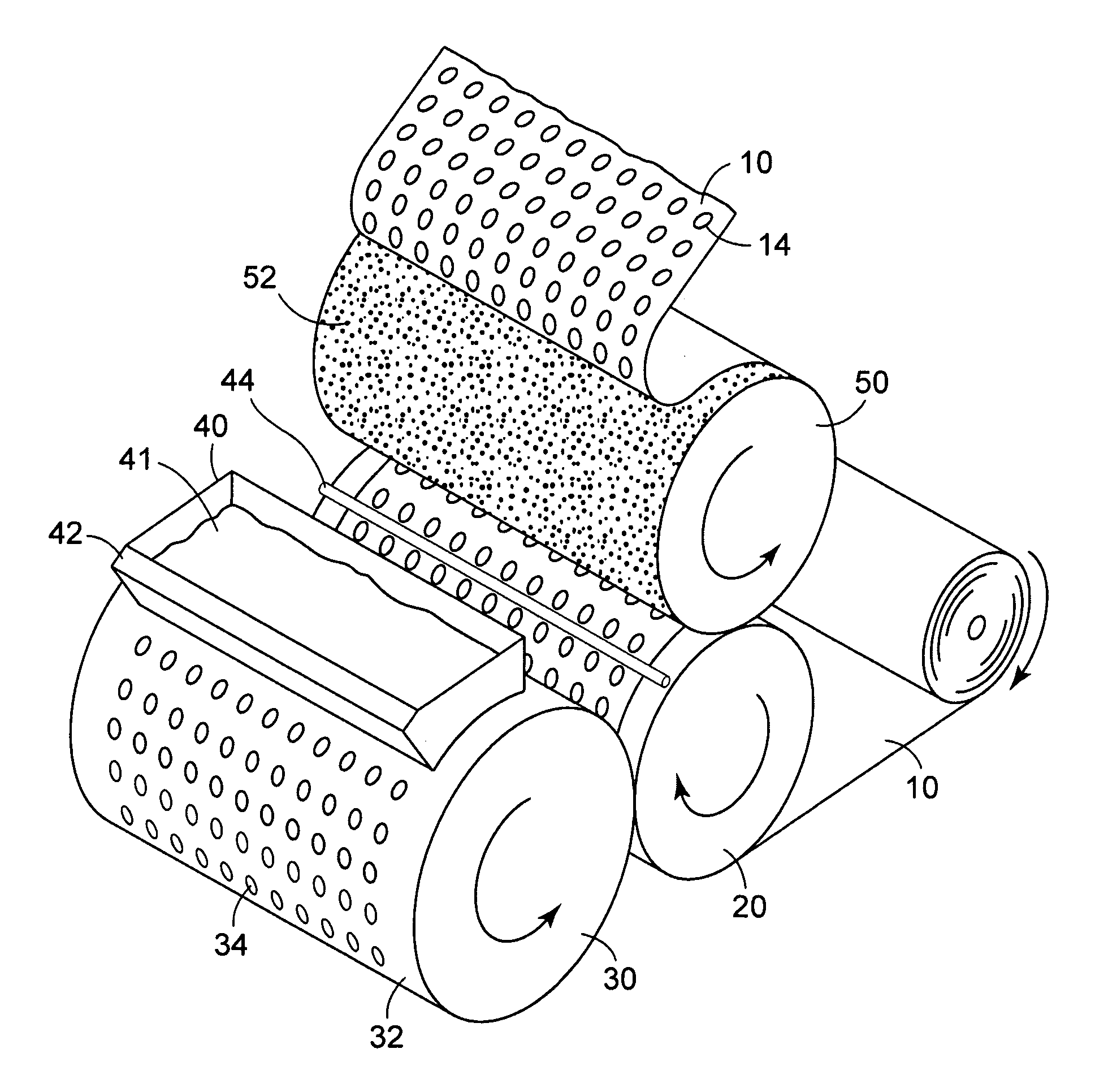
[0130]A web of the present invention was produced using apparatus similar to that shown in FIG. 8. A 5 cm diameter single screw extruder was used to deliver molten ultra low density polyethylene (ENGAGE 8402, 30 MI, DupontDow Elastomers), pigmented with 1.5% of a yellow polyolefin-based color concentrate, at a melt temperature of approximately 273° C. to a strand die 40 having 5 orifices spaced 25 mm apart across the die tip. Each orifice was 2.0 mm in diameter. The strands of molten polymer were extruded vertically downward onto the exterior surface 32 of an oil-heated steel transfer roll 30 having a diameter of 23 cm. The exterior surface of the transfer roll was machined using a computer controlled milling machine to have truncated hemispherical depressions 2.3 mm in diameter and 1.3 mm in depth, having a volume of 2.2 mm3 and an area of 3.2 mm2 arranged in a staggered array with center-to-center spacing between depressions of 5.1 mm resulting in 3.9 depressions / cm2 across the ex...

example 2

[0135]To demonstrate the use of a transfer roll having larger sized depressions, a web was prepared as in Example 1 except the exterior surface of the transfer roll was machined using a computer controlled milling machine to have elongated hemispherical depressions 2.3 mm in diameter and 2.3 mm in depth, having a volume of 6.6 mm3 and an area of 3.2 mm2 arranged in a staggered array with center-to-center spacing between depressions of 5.1 mm resulting in 3.9 depressions / cm2 across the exterior surface of the transfer roll. The basis weight of each transferred molten polymer region was 102 grams / m2. The cumulative basis weight of the transferred polymer regions on the nonwoven substrate was 8.0 grams / m2. The temperature of the backup roll was approximately 121° C. and the temperature of the forming roll was approximately 38° C. The height of the stems produced by the forming roll, measured normal to the surface of the base polymer region, was 280 microns.

example 3

[0136]To demonstrate the use of a transfer roll having larger sized depressions, a web was prepared as in Example 1 except the exterior surface of the transfer roll was machined using a computer controlled milling machine to have elongated hemispherical depressions 2.5 mm in diameter and 2.5 mm in depth, having a volume of 12.9 mm3 and an area of 5.1 mm2 arranged in a staggered array with center-to-center spacing between depressions of 5.1 mm resulting in 3.9 depressions / cm2 across the exterior surface of the transfer roll. The basis weight of each transferred molten polymer region was 221 grams / m2. The cumulative basis weight of the transferred polymer regions on the nonwoven substrate was 28 grams / m2. The temperature of the backup roll was approximately 121° C. and the temperature of the forming roll was approximately 38° C. The height of the stems produced by the forming roll, measured normal to the surface of the base polymer region, was 381 microns.


PUM

PropertyMeasurementUnit
volumeaaaaaaaaaa
areaaaaaaaaaaa
lengthsaaaaaaaaaa

Abstract

Systems and methods for manufacturing composite webs including a substrate with one or more discrete polymeric regions located thereon are disclosed. The discrete polymeric regions are deposited by transferring molten thermoplastic composition from depressions on a transfer roll to a substrate. Each of the discrete polymeric regions is further formed to include multiple structures formed thereon. Those structures may include, for example, stems (capped or otherwise), hooks (as part of a hook and loop fastening system), pyramids, etc.

Description

FIELD OF THE INVENTION[0001]The present invention relates to systems and methods for manufacturing composite webs that include structured discrete polymeric regions on at least one surface thereof.BACKGROUND[0002]The manufacture of articles that include thermoplastic structures useful to, e.g., fasten articles together (hook and loop systems, capped stems, etc.) are known. Such processes, however, typically provide thermoplastic structures that are located over an entire substrate or web. Where smaller, discrete regions of fastening or other structures are required, pieces of the preformed thermoplastic structures are often attached to a separate article, e.g., the fastening tab of a diaper or incontinence garment.[0003]The handling and attachment of such discrete pieces can, however, be problematic, by potentially reducing throughput, causing waste (where the discrete pieces are not securely attached), etc. The discrete pieces may also present relatively sharp edges that may be the...

Claims


Application Information

Patent Timeline
Patent Type & Authority Patents(United States)
IPC IPC(8): D01D5/20B05D1/28B05D7/24B29C43/22B29C43/28D04H1/70D06M15/227D06M15/564
CPCB29C43/222B29C43/28B29L2031/729B29C43/22
Inventor SEIDEL, DAVID L.TUMAN, SCOTT J.
Owner 3M INNOVATIVE PROPERTIES CO
Why Eureka
Try Eureka