
Powder compacting method, powder compacting apparatus and method for producing rare earth magnet

a powder and compacting technology, applied in the direction of magnets, applications, manufacturing tools, etc., can solve the problems of difficult to obtain a quality compact from this alloy powder, compact may crack, chip or deform, and the problem of particular noticeable problems

Inactive Publication Date: 2006-05-02
HITACHI METALS LTD
View PDF17 Cites 15 Cited by
  • Summary
  • Abstract
  • Description
  • Claims
  • Application Information

AI Technical Summary

Benefits of technology

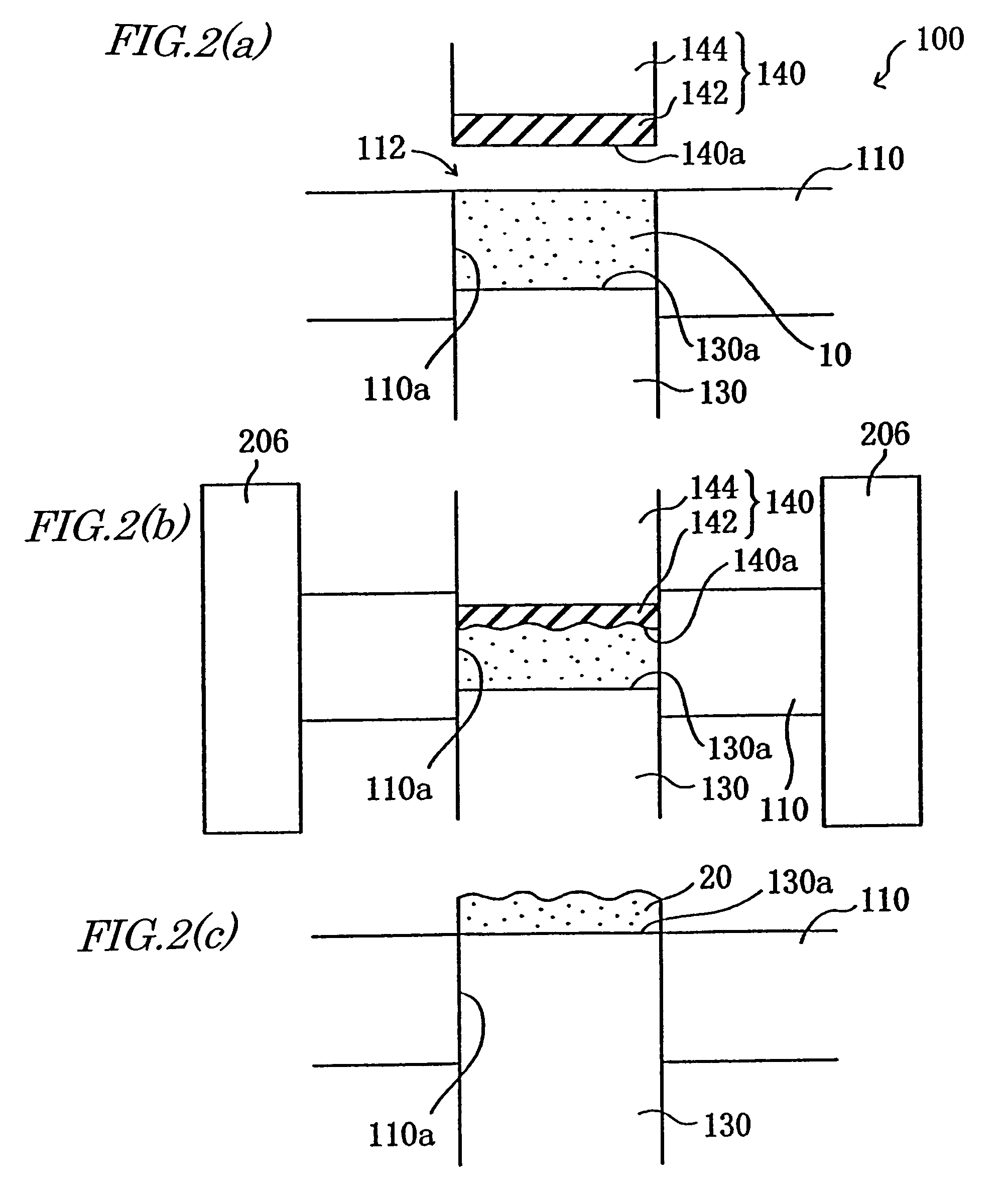
[0044]In another preferred embodiment, the upper press surface is the surface of a resin layer, and the upper punch includes a member for preventing the resin layer from expanding in a horizontal direction, which is perpendicular to the press axis direction, under the compacting pressure.
[0045]In another preferred embodiment, the upper punch includes a concave portion to receive the resin layer, and the side surface of the concave portion prevents the resin layer from expanding in the horizontal direction that is perpendicular to the press axis direction under the compacting pressure.

Problems solved by technology

However, it is particularly difficult to obtain a compact of quality from this alloy powder.
And if such a density variation is significant, then the compact may crack, chip or deform as a result.
This problem is particularly noticeable in a compact with a low density.
Also, a thin compact is considerably affected by the distribution in the shrinkage rate, easily cracks or chips, and is likely deformed significantly.
Unfortunately, though, the rubber pressing method is a sort of hydrostatic pressure pressing process with very low productivity and is hard to apply industrially.
In the pressing method disclosed in Japanese Patent Gazette for Opposition No. 55-26601, however, if a powder material with a low fill density, which has been loaded by a natural loading technique, for example, is pressed, then the resultant compact likely cracks, chips or deforms.
According to this method, however, the magnetic powder material 10 likely has a non-uniform fill density distribution while being loaded into such a rubber mold at a high density.
But since the outer shape of the compact 20 reflects its fill density distribution, it is difficult to obtain a compact in a predetermined shape.
Also, this method requires high-density filling.
As a result, the problem becomes even more noticeable.
In particular, none of those techniques can compact a powder material with a low fill density (e.g., the rare earth alloy powder material described above) at a high productivity.

Method used


Image

  • Powder compacting method, powder compacting apparatus and method for producing rare earth magnet
  • Powder compacting method, powder compacting apparatus and method for producing rare earth magnet
  • Powder compacting method, powder compacting apparatus and method for producing rare earth magnet

Examples


Embodiment Construction

[0066]Hereinafter, embodiments of a powder compacting method and apparatus according to the present invention will be described with reference to the accompanying drawings.

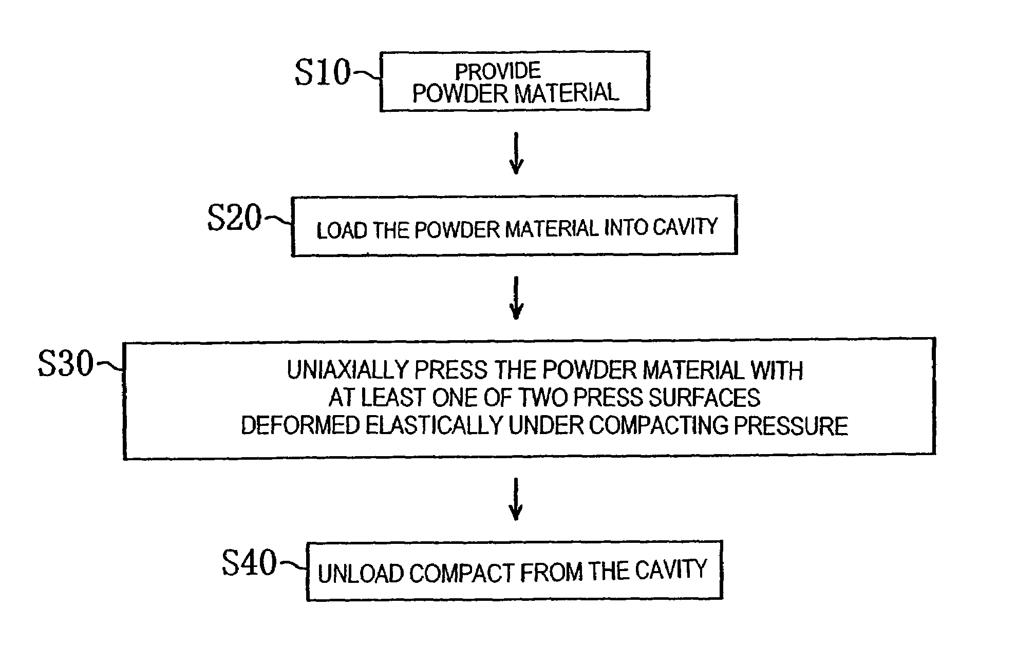
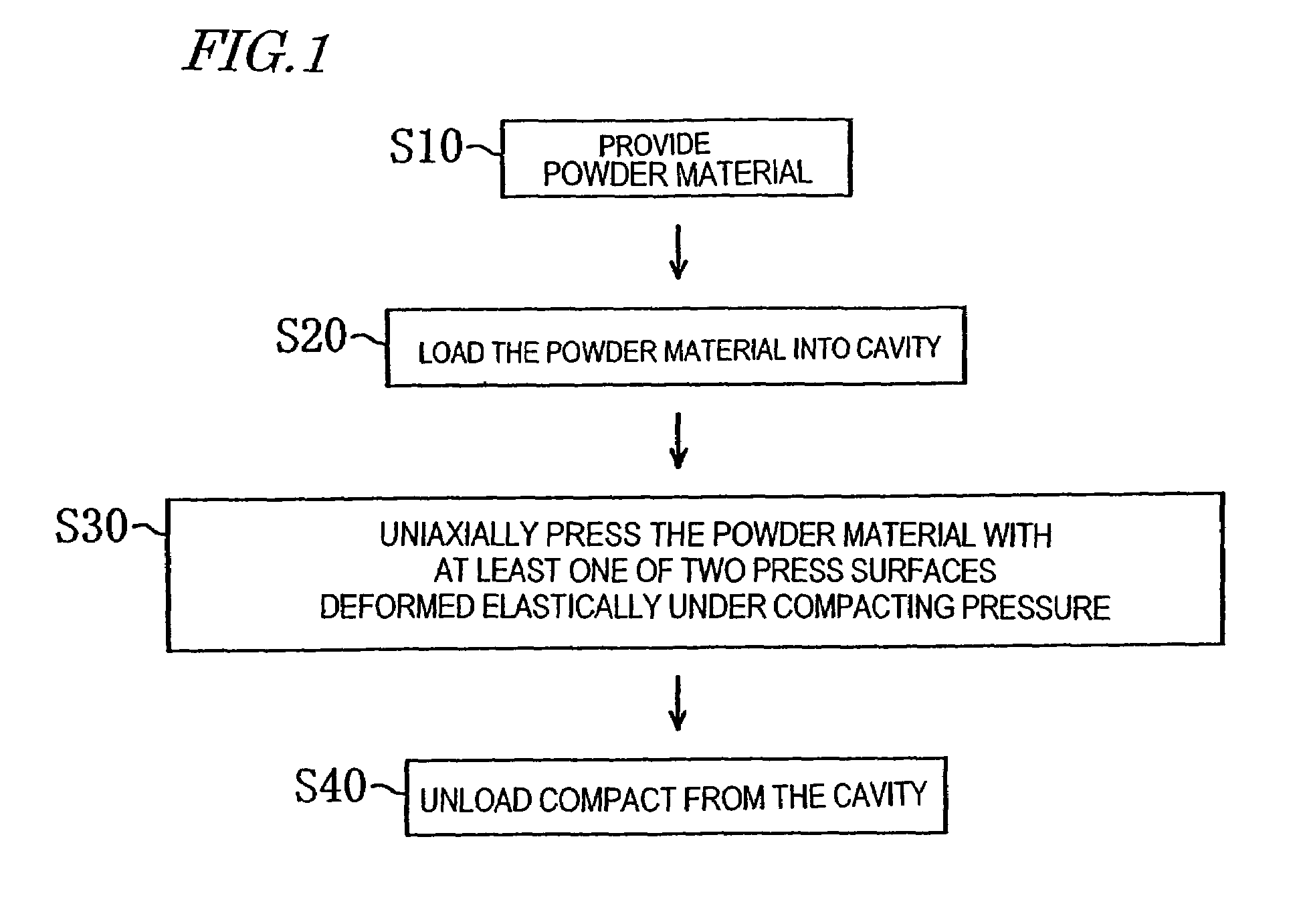
[0067]As shown in the flowchart of FIG. 1, a powder compacting method according to an embodiment of the present invention includes: the step S10 of providing a powder material; the step S20 of loading the powder material into a cavity; the step S30 of uniaxially pressing the powder material with at least one of two press surfaces deformed elastically under a compacting pressure; and the step S40 of unloading a compact from the cavity. In the uniaxially pressing step S30, at least one of two opposed press surfaces, contacting with the powder material in the cavity, is deformed elastically under the compacting pressure.

[0068]That is to say, in the powder compacting method of the present invention, at least one of the two press surfaces (i.e., both or one of the two press surfaces) is deformed elastically under the c...


PUM

PropertyMeasurementUnit
temperatureaaaaaaaaaa
mean particle sizeaaaaaaaaaa
particle sizeaaaaaaaaaa

Abstract

A powder compacting method includes the steps of: providing a powder material; loading the powder material into a cavity; uniaxially pressing the powder material, which has been loaded into the cavity, between two opposed press surfaces, thereby obtaining a compact, wherein at least one of the two press surfaces is deformed elastically under a compacting pressure when contacting with the powder material in the cavity; and unloading the compact from the cavity. According to this powder compacting method, even when the powder material has a non-uniform fill density distribution, a compact with a uniform density distribution can be obtained at a high productivity.

Description

TECHNICAL FIELD[0001]The present invention relates to a method and apparatus for compacting a powder and a method for producing a magnet. More particularly, the present invention relates to a powder compacting method and apparatus that can be used effectively to compact a rare earth alloy powder and also relates to a method for producing a magnet out of a rare earth alloy powder.BACKGROUND ART[0002]A powder compacting technique is used to manufacture various types of parts to be made of a ceramic or a metal. For example, a sintered body of a ceramic or a metal is manufactured by sintering a compact that has been obtained in a predetermined shape by subjecting a powder material to a powder compaction process. By subjecting the sintered bodies to a finishing process thereafter to adjust the sizes and shapes thereof, final products are obtained.[0003]Generally speaking, the quality of a sintered body (in terms of physical properties or configuration) is determined by the quality of a c...

Claims


Application Information

Patent Timeline
Patent Type & Authority Patents(United States)
IPC IPC(8): B22F1/00B22F1/02B22F3/02B30B15/02B30B15/06H01F41/02
CPCB22F3/02B30B15/024H01F41/0273H01F41/0266B30B15/065
Inventor OGAWA, ATSUSHI
Owner HITACHI METALS LTD
Learn More