Antenna arrangement with adjustable radiation pattern and method of operation

a radiation pattern and antenna technology, applied in the direction of antennas, antenna feed intermediates, electrical devices, etc., can solve the problems of inability to match location-specific characteristics, inability to change the angle of the antenna, and the complexity of the antenna arrangement is enormous, so as to achieve the effect of low power level, higher transmission intensity, and lower power level

Inactive Publication Date: 2006-05-02
TELEFON AB LM ERICSSON (PUBL)
View PDF39 Cites 27 Cited by
  • Summary
  • Abstract
  • Description
  • Claims
  • Application Information

AI Technical Summary

Benefits of technology

[0014]The technology herein makes it possible, for example, to produce asymmetric horizontal polar diagrams, to be precise even when considered in the far field. It is also possible to produce horizontal polar diagrams for which, although they are symmetrical, that is to say they are arranged symmetrically with respect to a plane that runs vertically with respect to the reflector plane, the transmission signals are emitted with only a comparatively low power level in this vertical plane of symmetry. It is thus also possible to produce, for example, two, four etc. main lobes that are symmetrical with respect to this plane but which transmit more to the left and more to the right with an angled alignment position and, in between them preferably in the plane which is vertical with respect to the reflector plane, and which would intrinsically correspond to the main emission plane in the normal case, with the antenna arrangement transmitting with a considerably lower power level.
[0015]However, it is equally possible to produce horizontal polar diagrams which, for example, have an odd number of main lobes and in this case, if required, are arranged symmetrically with respect to a plane which runs at right angles to the reflector plane. In this case, one main lobe direction may preferably be located in the vertical plane of symmetry, or in a plane at right angles to the reflector plane. At least one further main lobe is in each case located on the left-hand side and on the right-hand side of the plane that is at right angles to the reflector plane. The intensity minima which are located between them may, for example, be reduced only by less than 10 dB, in particular by 6 dB or less than 3 dB. The antenna arrangement according to the illustrative exemplary non-limiting implementation and its operation thus make it possible to illuminate specific zones with a higher transmission intensity, depending on the special features on site, and in the process effectively to “mask out” other areas, or to supply them with only reduced radiation intensity. This offers advantages particularly when the horizontal polar diagram is adapted in areas in which there are schools, kindergartens etc., such that these areas are illuminated only very much more weakly.

Problems solved by technology

However, such a change to a down-tilt angle is not the only or adequate solution for all situations.
In this case, matching to location-specific characteristics is impossible since it is not possible to change the polar diagram in the horizontal direction retrospectively.
Antenna arrangements such as these are, however, enormously complex in terms of the antenna supply lines between the base station on the one hand and the antenna or the antenna elements on the other hand, with a dedicated feed cable being required for each column, and with two high-quality antenna cables being required for each column for so-called dual-polarized antennas, which are polarized at +45° and −45°, with an X-shaped alignment.
This leads to a high cost price and to expensive installation.
Finally, the base station also needs to have very complex algorithm circuits, thus once again increasing the overall costs.

Method used


Image

  • Antenna arrangement with adjustable radiation pattern and method of operation
  • Antenna arrangement with adjustable radiation pattern and method of operation
  • Antenna arrangement with adjustable radiation pattern and method of operation

Examples


Embodiment Construction

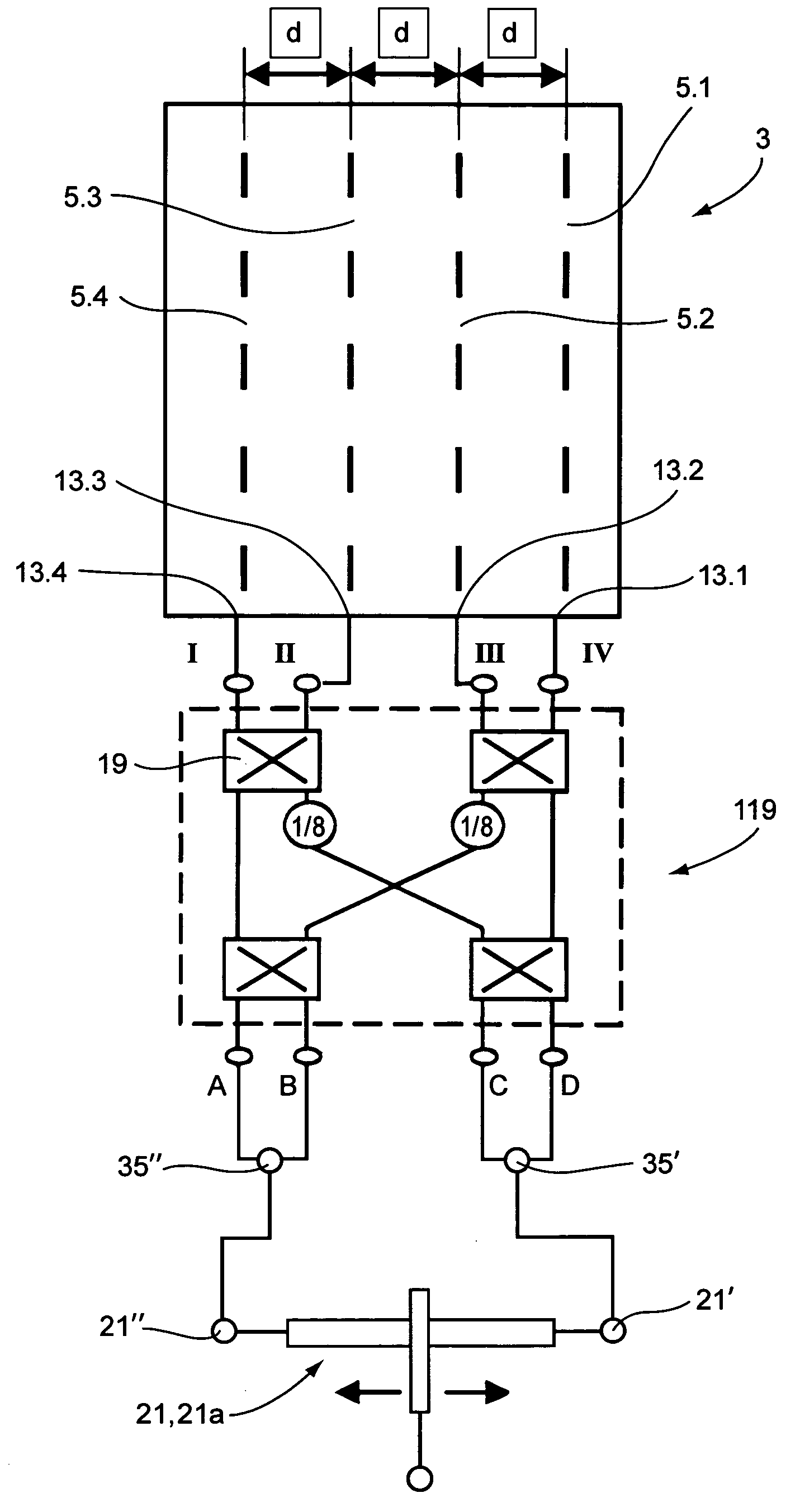
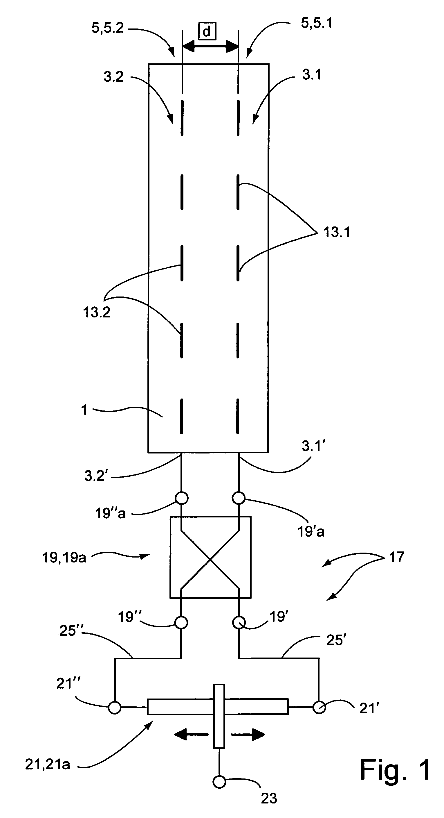
[0050]The antenna arrangement shown in FIG. 1 has a reflector 1, in front of which two antenna systems 3.1, 3.2 are formed. In the illustrated exemplary non-limiting implementation, the antenna arrangement has two columns 5, that is to say a column 5.1 and a column 5.2, in each of which respective antenna elements 13.1 and 13.2 are arranged. In the illustrated exemplary non-limiting implementation, these antenna elements 13.1 and 13.2 may, for example, each be formed from five dipole antenna elements which are arranged one above the other, are aligned vertically and, in the illustrated exemplary non-limiting implementation, are arranged in the two columns at the same height and with a lateral separation d which can be predetermined. An antenna arrangement is thus described which, by way of example, transmits and receives in one polarization plane in one frequency band.

[0051]The antenna arrangement in the illustrated exemplary non-limiting implementation is fed via a network 17 which...


PUM


Abstract

An improved antenna arrangement is distinguished by the following features: at least two antenna element systems are provided and each has at least one antenna element, which are arranged offset with respect to one another, at least in the horizontal direction, the at least two antenna element systems transmit and receive at least in one common polarization plane, a network is provided, via which the at least two antenna element systems can be supplied with a signal (Ain1, Ain2) with an intensity or amplitude which can be set differently or which can be adjusted relative to one another and preferably with a different phase angle.

Description

FIELD[0001]The technology herein relates to an antenna arrangement and to a method for its operation.BACKGROUND AND SUMMARY[0002]The mobile radio antennas provided for a base station normally have an antenna arrangement with a reflector in front of which a large number of antenna elements are provided, offset with respect to one another in the vertical direction. These antenna elements may, for example, transmit and receive in one polarization or in two mutually perpendicular polarizations. The antenna elements may be designed to receive in only one frequency band. The antenna arrangement may, however, also be in the form of a multiband antenna, for example for transmitting and receiving in two frequency bands with an offset with respect to one another. In principle, so-called triband antennas are also known.[0003]As is known, mobile radio networks have a cellular form, with each cell having a corresponding associated base station with at least one mobile radio antenna for transmitt...

Claims


Application Information

Patent Timeline
Patent Type & Authority Patents(United States)
IPC IPC(8): H01Q3/26H01Q3/32H01Q9/16H01Q19/17H01Q21/00
CPCH01Q19/17H01Q3/32
Inventor GABRIEL, ROLANDGOTTL, MAXIMILIANLANGENBERG, JORGRUMOLD, JURGEN
Owner TELEFON AB LM ERICSSON (PUBL)
Why Eureka
Try Eureka