
Liquid crystal display apparatus

a technology of liquid crystal display and display device, which is applied in the direction of instruments, computing, electric digital data processing, etc., can solve the problem of extremely large and achieve the effect of reducing the capacity of memory storing luts

Active Publication Date: 2006-05-02
UNIFIED INNOVATIVE TECH
View PDF14 Cites 36 Cited by
  • Summary
  • Abstract
  • Description
  • Claims
  • Application Information

AI Technical Summary

Benefits of technology

[0013]The present application is made for solving the foregoing problems, and an object of an embodiment of the present application is to reduce the capacity of memory storing LUTs by use of interpolation operations. Another object may be to provide a liquid crystal display apparatus that carries out an appropriate overshoot-driving in accordance with additional conditions such as temperature for example so as to carry out natural and high-speed display.
[0017]In view of the deficiency, the look-up tables of an embodiment of the present application are prepared so that the thinning is carried out with respect to gradations. Accordingly, it is possible to much further reduce the capacity of memory, as compared with the case where the applied voltages corresponding to all the gradations are found.
[0019]It is preferable that the applied gradation value acquiring section carries out an interpolation operation by use of a local coordinate system defined by respective axes for the current gradation and the desired target gradation. In this case, since the local coordinate system is adopted, the accuracy of interpolation improves, accordingly.
[0022]Thus, despite of the consideration of at least one additional condition, since the look-up tables are prepared so that the thinning is carried out with respect to the additional conditions, it is possible to appropriately carry out the overshoot-driving in accordance with the additional condition without increasing the capacity of memory, thereby making it possible to carry out the natural and high-speed display.

Problems solved by technology

This causes the problem that the capacity of the memory storing the LUTs becomes extremely large.

Method used


Image

  • Liquid crystal display apparatus
  • Liquid crystal display apparatus
  • Liquid crystal display apparatus

Examples


first embodiment

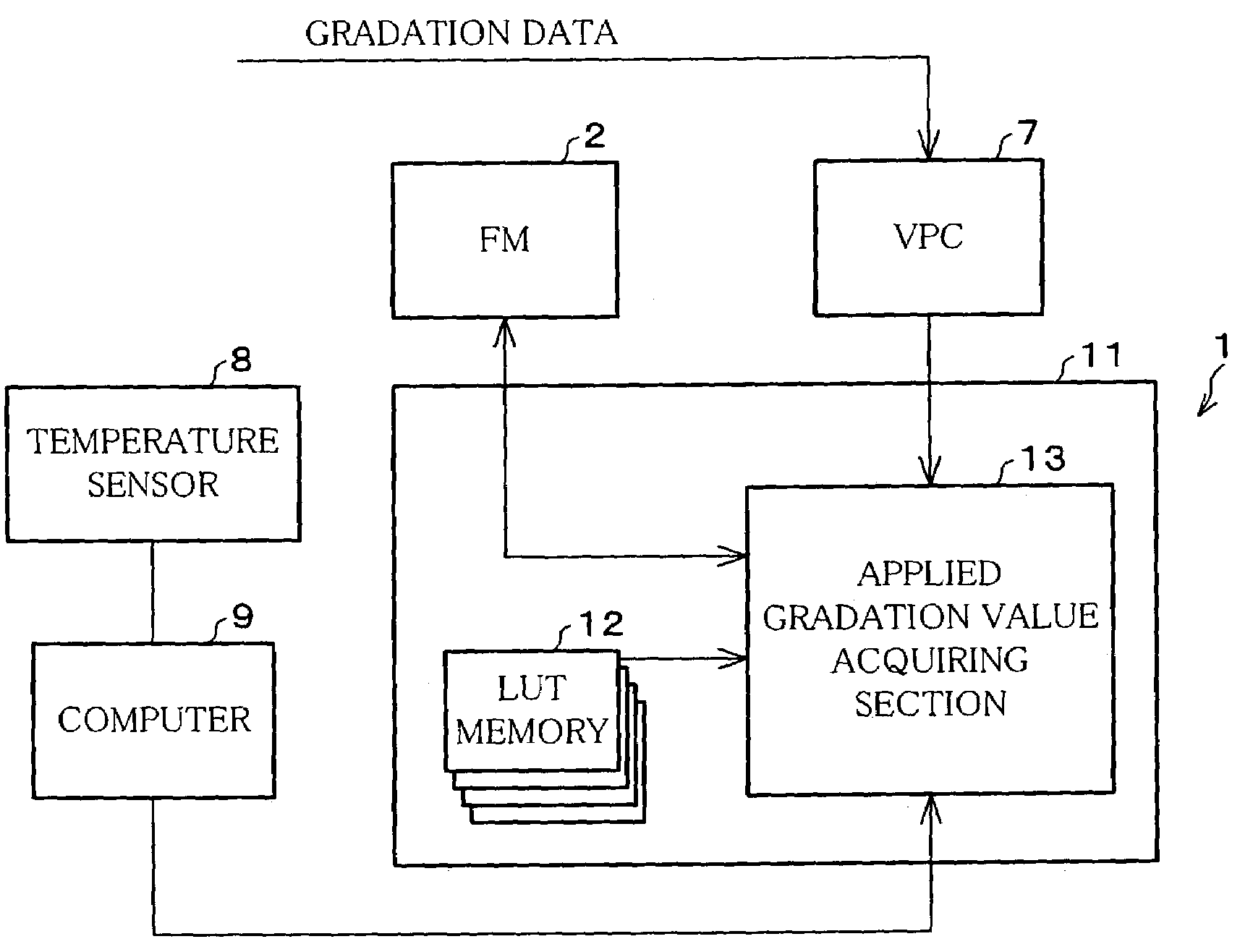
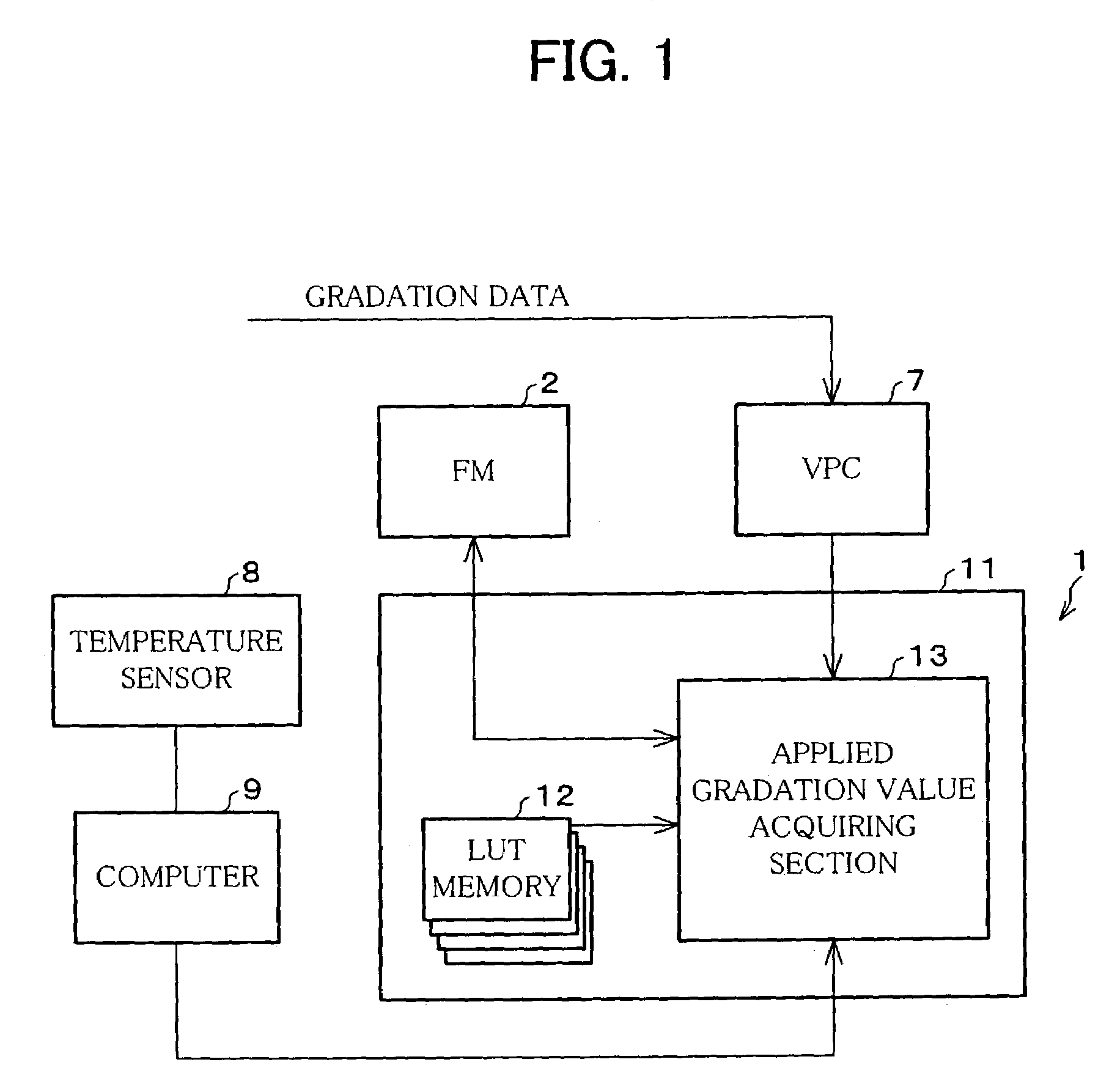
[0032]The following description deals with an embodiment of the present invention with reference to FIGS. 1 through 4. Note that the present invention is not limited to the description.

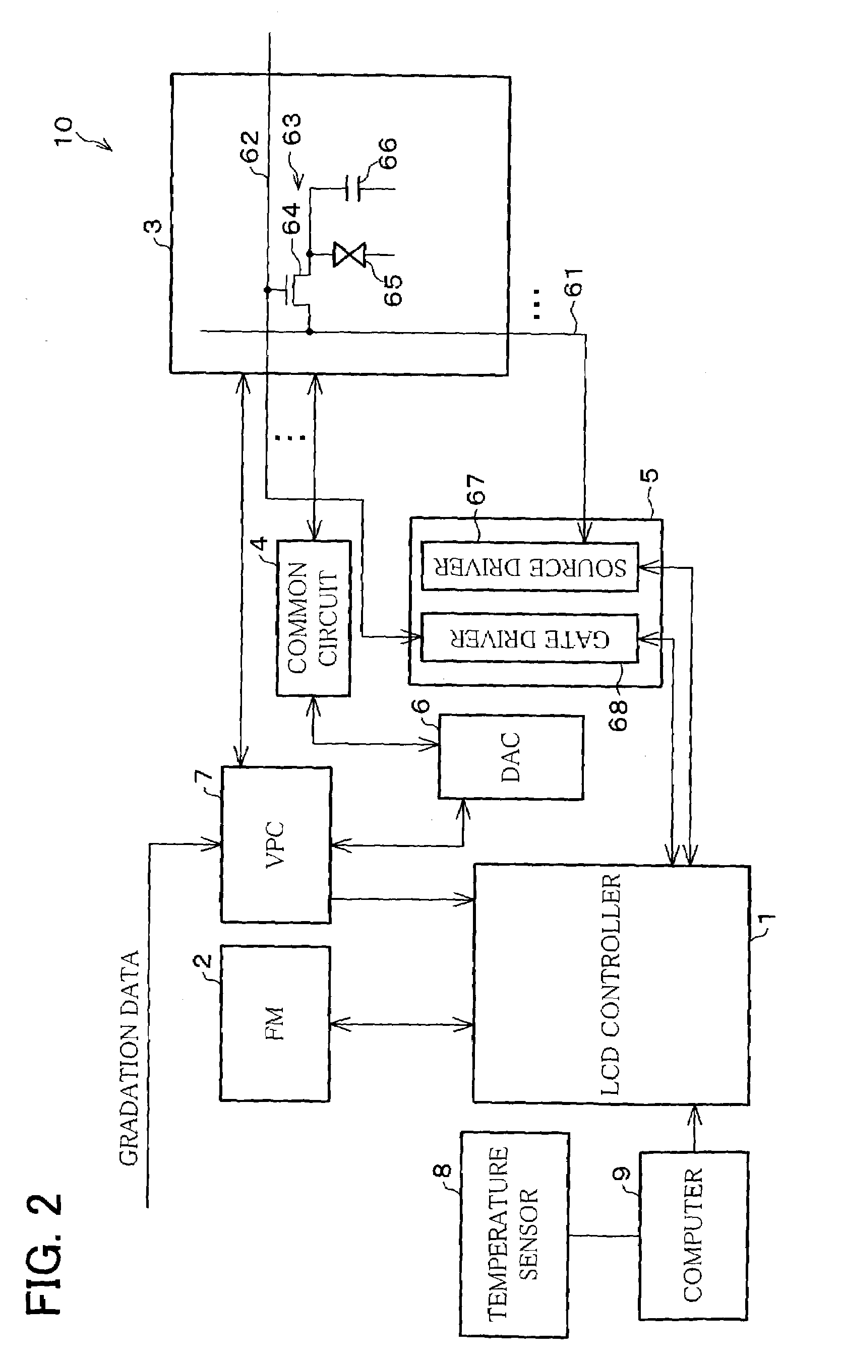
[0033]FIG. 2 is a block diagram showing an arrangement of a liquid crystal display apparatus (LCD 10) in accordance with the present embodiment.

[0034]The LCD 10 includes a liquid crystal panel 3, a common circuit 4, a gradation circuit 5, a digital / analog converter (DAC) 6, an LCD controller 1, a frame memory (FM) 2, a video processing controller (VPC) 7, a temperature sensor 8, and a computer 9.

[0035]The liquid crystal panel 3 includes a substrate (screen) on which pixels are provided. For instance, a plurality of source bus lines 61 are provided so as to be parallel to each other in the longitudinal direction of the screen, and a plurality of scanning lines 62 are provided so as to be parallel to each other in the transverse direction of the screen.

[0036]The source bus lines 61 and the scanning line...

second embodiment

[0091]The following description deals with another embodiment. Note that the same reference numerals are assigned to the members having the same functions as those of the first embodiment, and the explanation thereof is omitted here.

[0092]According to the second embodiment, the interpolation operation is carried out in accordance with a local coordinate system that concurrently uses Tables 1 and 2. Such a local coordinate system for the interpolation operation is shown, for example, in FIG. 5.

[0093]As shown in FIG. 5, in the local coordinate system having three axes for target gradation value, current gradation value, temperature value, respectively, an additional axis (ζ-axis) is further provided in addition to the foregoing target gradation local axis (ξ-axis) and the current gradation local axis (η-axis) so as to form three-dimensional local coordinate system, the ζ-axis being orthogonal to the ξ-axis and the η-axis.

[0094]Note for easier understanding that the following descripti...

third embodiment

[0116]The following description deals with a further embodiment of the present invention. Note that the same reference numerals are assigned to the members having the same functions as those of the respective first and second embodiments. The explanation thereof will be omitted here.

[0117]In Procedure 1 (the first interpolation operation) of the first embodiment, when the interpolation equation is defined by a quadratic expression for (ξ, η), the interpolation equation is represented by aξ2+bη2+cξη+dξ+eη+f=H. In order to find the first interpolation value H, totally six unknowns (a, b, c, d, e, and f) should be found. Thus, it is necessary to acquire at least six points in the local coordinate shown in FIG. 6 to find such three unknowns.

[0118]In this case, like Procedure 1 of the first embodiment, in order to find the first interpolation value H corresponding to a point P31, an area (area A enclosed by points P21, P22, and P23) that includes the point P31 is selected from an area de...


PUM


Abstract

A liquid crystal display apparatus includes an applied gradation value acquiring section for receiving gradation data of a frame to be displayed, gradation data of a frame to be outputted, gradation data of the current frame supplied from a frame memory and measured data from a temperature sensor. An interpolation operation is then carried out in reference to look-up tables stored in a look-up table memory so as to calculate a target applied gradation data required for gradation display. The section sets for each LUT (a) a coordinate system in which a lattice point is represented by a combination of the gradation data of the current frame and the gradation data of the target frame and (b) a local coordinate system having lattice points corresponding to the target gradation data in the coordinate system; carries out interpolation operation by use of the local coordinate system, and carries out further interpolation operation based on the interpolated value (table interpolated value), in accordance with the measured data so as to calculate the target applied gradation data. The adoption of the interpolation by use of the local coordinate system enables the finding of the target applied gradation data (interpolated value) with higher accuracy, while a variety of additional conditions are taken into consideration.

Description

[0001]The present application hereby claims priority under 35 U.S.C. §119 on Japanese patent application number 2002-84225 filed Mar. 25, 2002, the entire contents of which are hereby incorporated by reference.FIELD OF THE INVENTION[0002]The present invention generally relates to a liquid crystal display apparatus. Preferably, it relates to one used in a television set, in an OA (Office Information) device, and as a monitor for a CAD (Computer Aided Design) system.BACKGROUND OF THE INVENTION[0003]A liquid crystal display apparatus has almost become an image display apparatus that is superior to a cathode ray tube because of (a) features such as small-footprint and power savings and (b) recent improvement in performance such as viewing angle, contrast, color reproducibility, and response speed. Thus, it is anticipated that such a liquid crystal display apparatus may be more often and widely applied to a monitor for a television set, office automation, etc. in future.[0004]In general,...

Claims


Application Information

Patent Timeline
Patent Type & Authority Patents(United States)
IPC IPC(8): G09G3/36G09G3/20
CPCG09G3/3648G09G3/2007G09G2340/16G09G2320/0252
Inventor SHIGETA, MITSUHIROSHIOMI, MAKOTOTOMIZAWA, KAZUNARIMIYATA, HIDEKAZU
Owner UNIFIED INNOVATIVE TECH
Learn More