Eureka AIR delivers breakthrough ideas for toughest innovation challenges, trusted by R&D personnel around the world.

Liquid crystal cell, display device, and particular method of fabricating liquid crystal cell by dropping and capillary action

a liquid crystal cell and display device technology, applied in non-linear optics, instruments, optics, etc., can solve problems such as interference with smooth liquid crystal injection, and achieve the effect of enhancing work efficiency and efficient bubble pumping

Inactive Publication Date: 2006-05-02
AU OPTRONICS CORP
View PDF2 Cites 34 Cited by
  • Summary
  • Abstract
  • Description
  • Claims
  • Application Information

AI Technical Summary

Benefits of technology

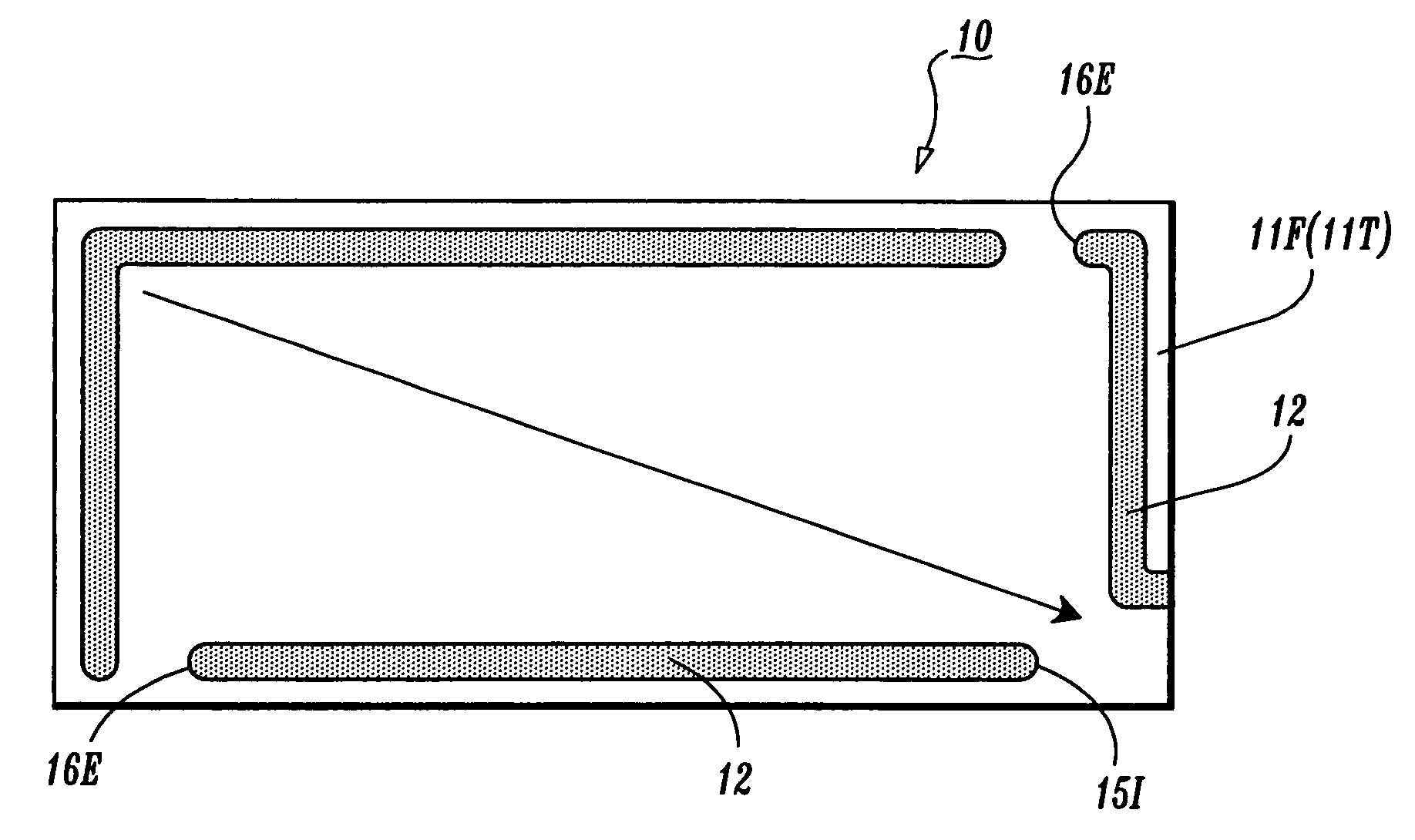
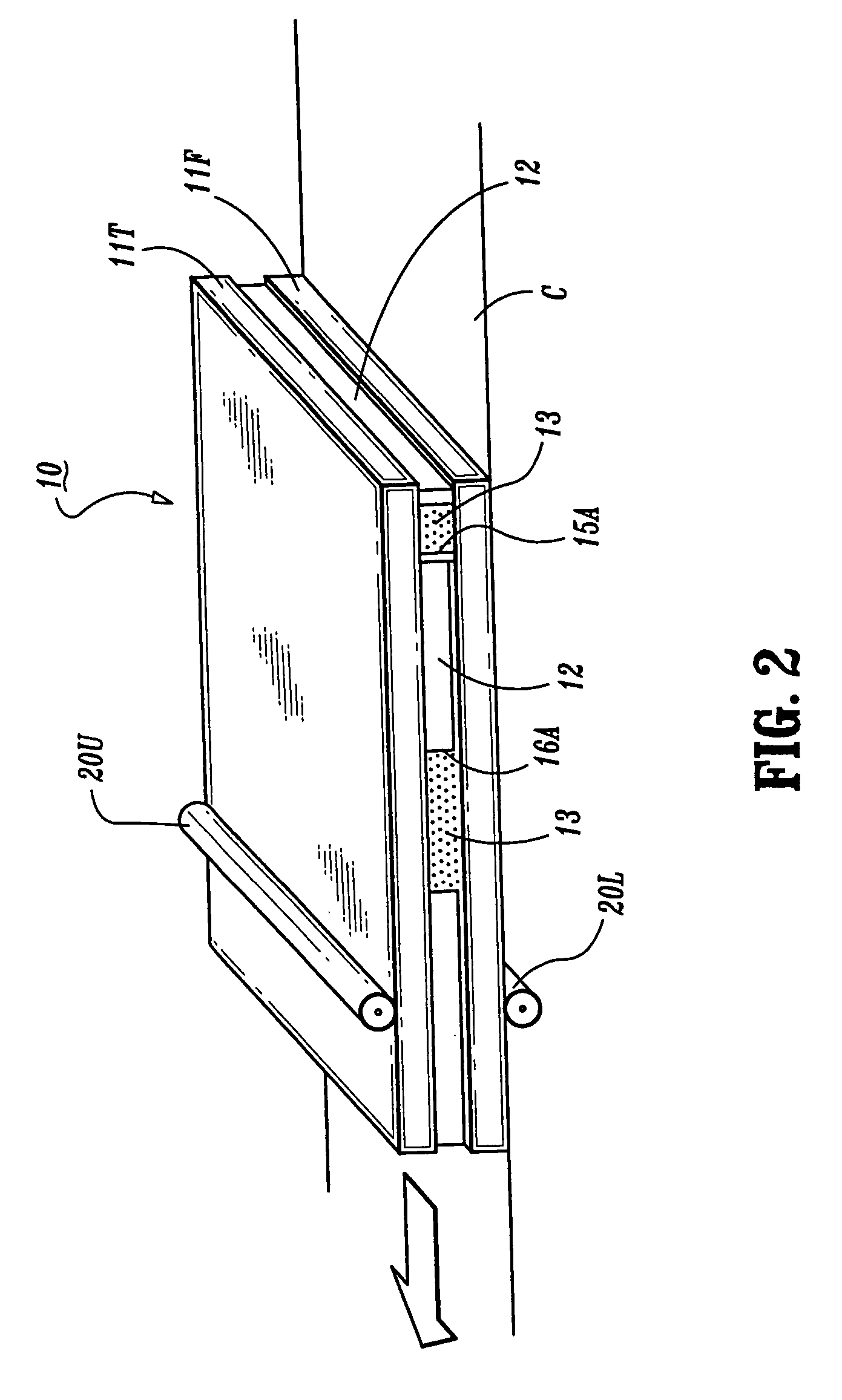
[0017]In order to achieve the foregoing object, a liquid crystal cell of the present invention comprises first and second openings formed on side faces of the liquid crystal cell, which communicate with a space filled with liquid crystal. In the first opening, a gap thereof is larger than a gap between two substrates in a region surrounded by a sealing portion because of a step formed with the region surrounded by the sealing portion by, for example a color filter or the like. Here, the gap between two substrates in the region surrounded by the sealing portion means a gap between electrode surfaces of, for example, a color filter, a TFT, and so on, provided in the both substrates. Because of the first opening, when the bubbles mixed in the liquid crystal during fabricating are pushed out from the first opening, the bubbles remaining with the liquid crystal in the first opening can be prevented from returning to the region surrounded by the sealing portion by the step portion.
[0026]In the third step, if liquid crystal is replenished from a side in a conveying direction set for conveying the liquid crystal cell, it is possible to prevent a dispenser or the like for replenishing liquid crystal from interfering with a mechanical unit such as a roller or the like for pushing-out bubbles.

Problems solved by technology

This step interferes with smooth liquid crystal injection.

Method used


Image

  • Liquid crystal cell, display device, and particular method of fabricating liquid crystal cell by dropping and capillary action
  • Liquid crystal cell, display device, and particular method of fabricating liquid crystal cell by dropping and capillary action
  • Liquid crystal cell, display device, and particular method of fabricating liquid crystal cell by dropping and capillary action

Examples


Embodiment Construction

[0041]Next, the present invention will be described in detail based on an embodiment shown in the accompanying drawings.

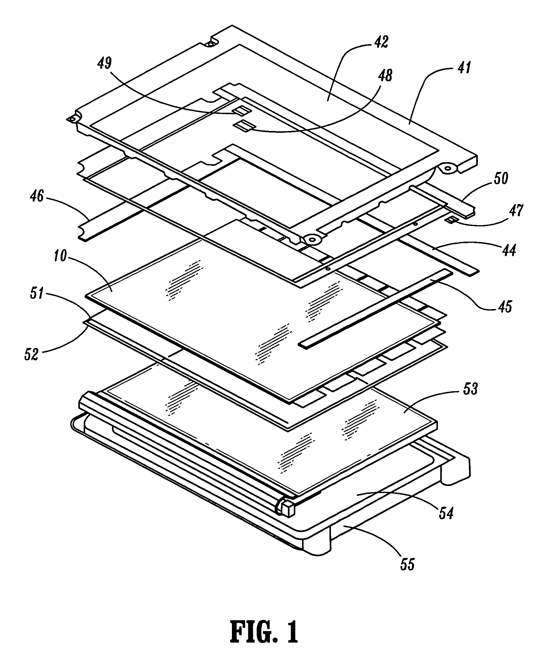
[0042]FIG. 1 is a perspective view for explaining an entire constitution of the display device according to an embodiment of the present invention. A reference numeral 41 denotes a metallic shield case for forming an upper frame, in which a display window 42 is formed to delimit a valid screen of a liquid crystal display module. A reference numeral 10 denotes a liquid crystal cell, comprising source and drain electrodes, a gate electrode, a TFT having an amorphous silicon layer or the like formed, a color filter, and so on, which are laminated between two glass substrates. Above the liquid crystal cell 10, a data driving circuit board 44, a gate driving circuit board 45, and an interface circuit board 46 are formed. Further, joiners 47, 48 and 49 are provided to connect these circuit boards. The circuit boards 44, 45 and 46 are fixed to the shield case 41 by interp...


PUM

PropertyMeasurementUnit
thicknessaaaaaaaaaa
diameteraaaaaaaaaa
thicknessaaaaaaaaaa

Abstract

Bubbles mixed in liquid crystal injected into a liquid crystal cell are pushed out through an outlet. The outlet has a space secured to a maximum limit by an extended sealing portion reaching the outer peripheral end surfaces of substrates, and a step with a color filter is formed. The pushed-out bubbles are surely trapped by the space of the outlet. In a replenishing port for replenishing liquid crystal, an introduction spacer having a height equal to that of the color filter is provided, and by a capillary phenomenon, liquid crystal for replenishment can be smoothly introduced into the liquid crystal cell.

Description

CROSS-REFERENCE TO RELATED APPLICATION[0001]This application is a divisional of U.S. application Ser. No. 09 / 907,087 filed on Jul. 17, 2001, now U.S. Pat. No. 6,678,029, the disclosure of which in its entirety is incorporated by reference herein.BACKGROUND OF THE INVENTION[0002]1. Technical Field[0003]The present invention relates to a liquid crystal cell, a display device, and a method of fabricating a liquid crystal cell suitably used for injecting liquid crystal into a cell.[0004]2. Discussion of Related Art[0005]There has been a remarkable progress in the popularization of a liquid crystal display device used as an image display device for a personal computer, or other various monitors. The liquid crystal display device of this kind is typically constructed in a manner that a backlight as a sheet light source for illumination is provided in the backside of a liquid crystal cell and, by irradiating a liquid crystal surface having a predetermined expanse to an entirely uniform bri...

Claims


Application Information

Patent Timeline
Patent Type & Authority Patents(United States)
IPC IPC(8): G02F1/1341G02F1/1335G02F1/13357G02F1/1339
CPCG02F1/1341G02F1/1339
Inventor SUZUKI, SHUNJI
Owner AU OPTRONICS CORP
Why Eureka
Eureka Blog
Learn More