Lithographic apparatus and device manufacturing method

a technology of lithographic projection and manufacturing method, which is applied in the direction of electrical equipment, printers, instruments, etc., can solve the problems of difficult mechanical control of the position of the substrate table, difficulty in adequately controlling the relative position, and/or orientation, etc., and achieves the effect of greater pressure changes

Inactive Publication Date: 2006-05-02
ASML NETHERLANDS BV
View PDF76 Cites 83 Cited by
  • Summary
  • Abstract
  • Description
  • Claims
  • Application Information

AI Technical Summary

Benefits of technology

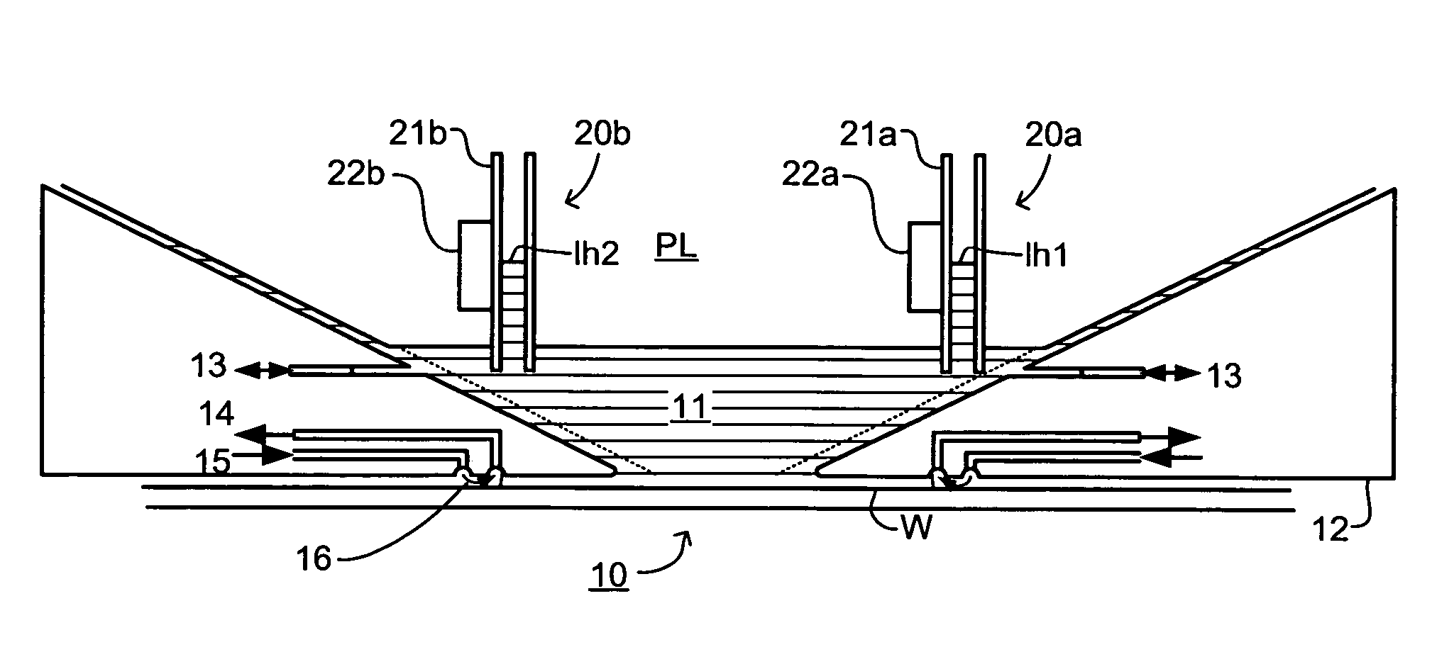
[0019]If liquid is confined in a space between a projection system and a substrate, change in the orientation and / or vertical position of the substrate may change the pressure of the liquid. Thus, measurement and / or determination of the pressure and / or height of the liquid may provide a simple result from which the orientation and / or vertical position of the substrate relative to the projection system, or at least changes in it, can be obtained. The exact relationship between pressure and / or height of the liquid and vertical height and / or orientation of the substrate will depend on the shape, size and nature of the liquid supply system and can be calculated or empirically derived for each application. For example, if the liquid supply system rigidly confines the liquid then changes in the orientation and / or vertical position of the substrate lead to greater pressure changes than if the liquid is more elastically confined.

Problems solved by technology

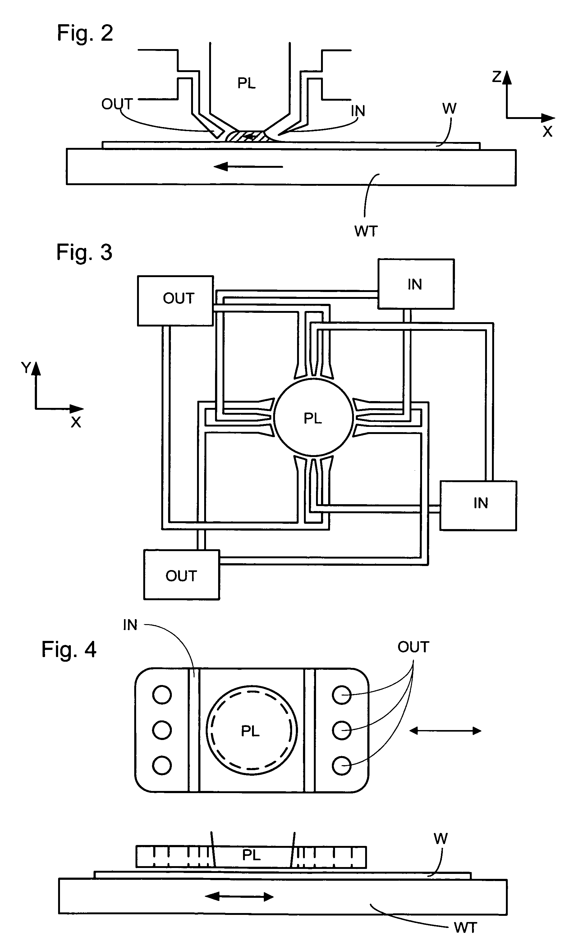
A possible problem with such immersion lithography apparatus is that it is difficult to adequately control the relative positions (including displacement and / or orientation) of the projection system and substrate table and hence the thickness of the liquid film between the projection system and the substrate.
Firstly, the substrate table and the projection system are hydrodynamically coupled so that the mechanical control of the substrate table position may be difficult and an accurate set point would be essential.
Secondly, the level (height) sensors used in conventional lithography apparatus typically are not compatible with a liquid reservoir.
Such sensors are generally based around a light beam that is reflected by the substrate at a relatively low angle of incidence and it is difficult to provide the necessary beam directing elements within the space occupied by the immersion liquid.

Method used


Image

  • Lithographic apparatus and device manufacturing method
  • Lithographic apparatus and device manufacturing method
  • Lithographic apparatus and device manufacturing method

Examples


Embodiment Construction

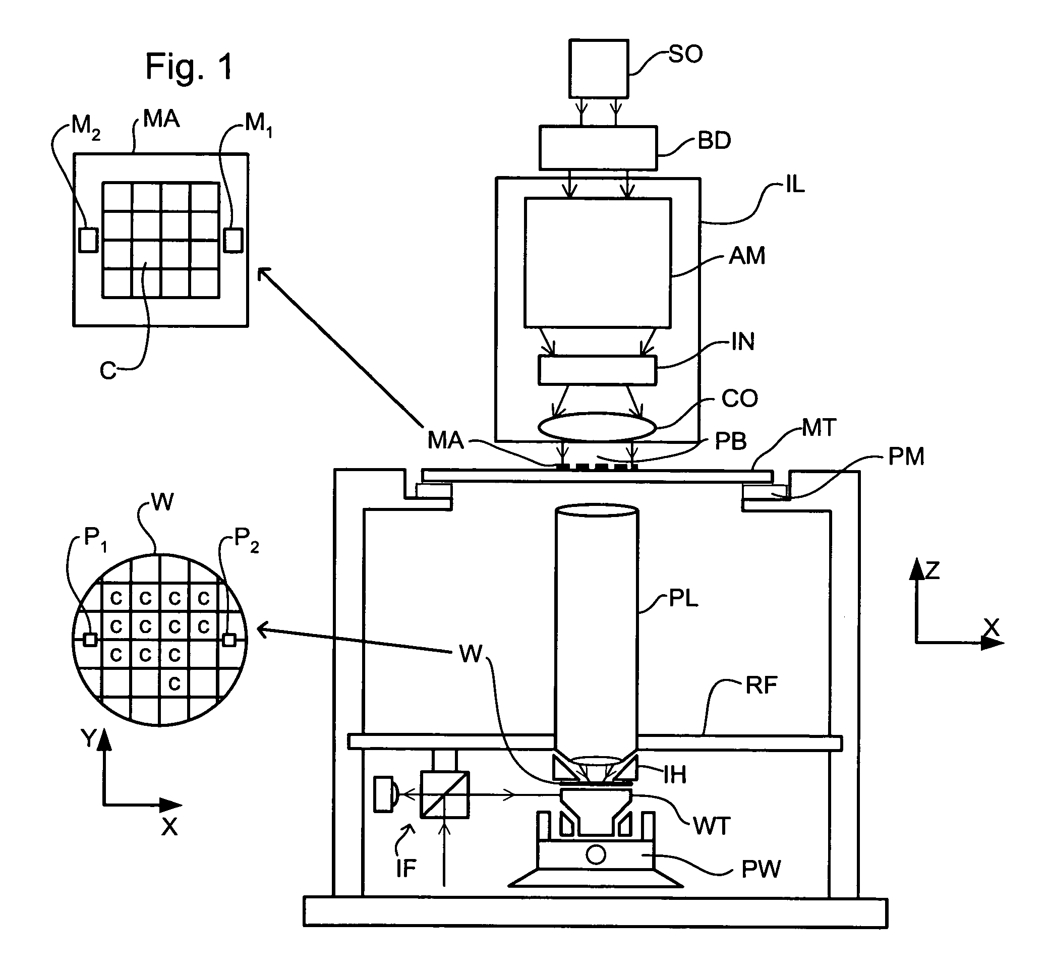
[0040]FIG. 1 schematically depicts a lithographic apparatus according to a particular embodiment of the invention. The apparatus comprises:[0041]an illumination system (illuminator) IL for providing a projection beam PB of radiation (e.g. UV radiation).[0042]a first support structure (e.g. a mask table) MT for supporting patterning device (e.g. a mask) MA and connected to first positioning device PM for accurately positioning the patterning device with respect to item PL;[0043]a substrate table (e.g. a wafer table) WT for holding a substrate (e.g. a resist-coated wafer) W and connected to second positioning device PW for accurately positioning the substrate with respect to item PL; and[0044]a projection system (e.g. a refractive projection lens) PL for imaging a pattern imparted to the projection beam PB by patterning device MA onto a target portion C (e.g. comprising one or more dies) of the substrate W.

[0045]As here depicted, the apparatus is of a transmissive type (e.g. employing...


PUM

PropertyMeasurementUnit
wavelengthaaaaaaaaaa

Abstract

The pressure and/or height of liquid in a liquid reservoir of an immersion lithography apparatus is obtained by a measurement device. The pressure and/or height can be used to determine the height and/or tilt of the substrate.

Description

[0001]This application claims priority from European patent application EP 03254139.3, filed Jun. 30, 2003, which is incorporated herein in its entirety.FIELD[0002]The present invention relates to a lithographic projection apparatus and a device manufacturing method.BACKGROUND[0003]A lithographic apparatus is a machine that applies a desired pattern onto a target portion of a substrate. Lithographic apparatus can be used, for example, in the manufacture of integrated circuits (ICs). In that circumstance, a patterning device, such as a mask, may be used to generate a circuit pattern corresponding to an individual layer of the IC, and this pattern can be imaged onto a target portion (e.g. comprising part of, one or several dies) on a substrate (e.g. a silicon wafer) that has a layer of radiation-sensitive material (resist). In general, a single substrate will contain a network of adjacent target portions that are successively exposed. Known lithographic apparatus include so-called ste...

Claims


Application Information

Patent Timeline
Patent Type & Authority Patents(United States)
IPC IPC(8): G03B27/52G03B27/42G03F7/20G03F9/00H01L21/027
CPCG03F7/70341G03F9/7034G03F9/7026
Inventor MULKENS, JOHANNES CATHARINUS HUBERTUSDERKSEN, ANTONIUS THEODORUS ANNA MARIALOF, JOERISIMON, KLAUSSTRAAIJER, ALEXANDERSTREEFKERK, BOB
Owner ASML NETHERLANDS BV
Why Eureka
Try Eureka