
Midspan patch panel with compensation circuit for data terminal equipment, power insertion and data collection

a compensation circuit and data terminal technology, applied in the direction of cross-talk/noise/interference reduction, electrical apparatus construction details, coupling device connections, etc., can solve the problems of limited progress in such areas, time-consuming and prone to further errors, and achieve the effect of reducing the adverse performance effect on communication

Active Publication Date: 2006-05-02
HUBBELL INC
View PDF39 Cites 27 Cited by
  • Summary
  • Abstract
  • Description
  • Claims
  • Application Information

AI Technical Summary

Benefits of technology

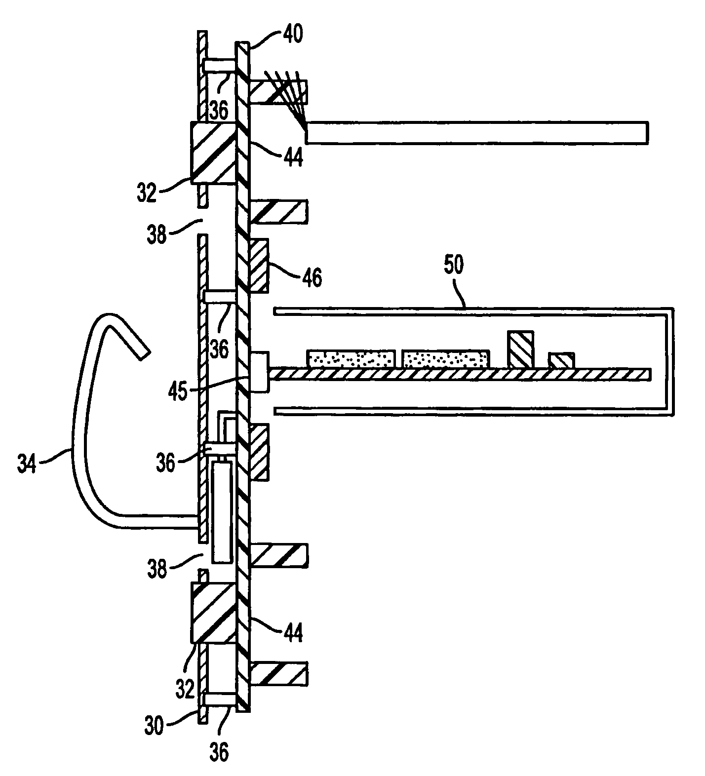
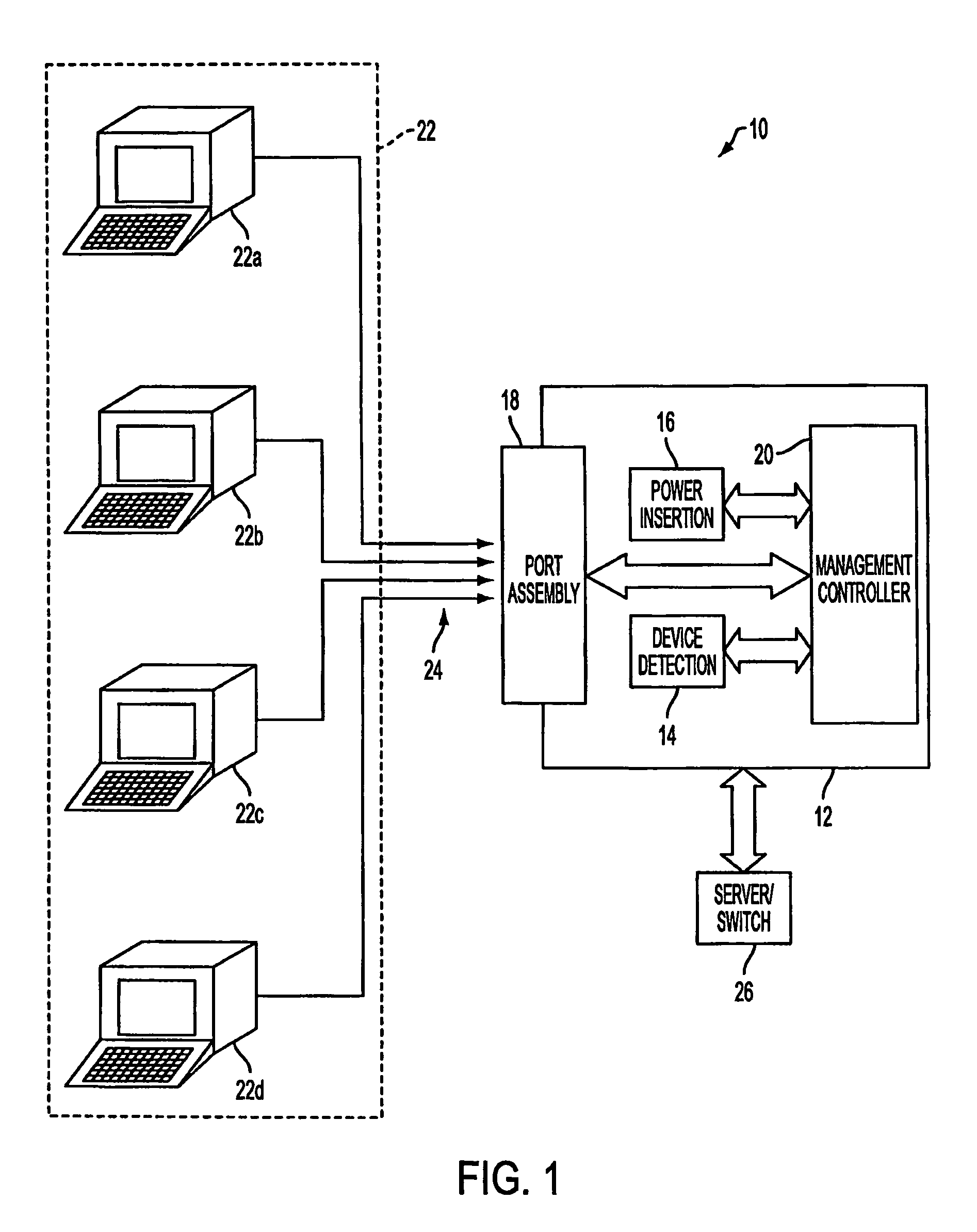
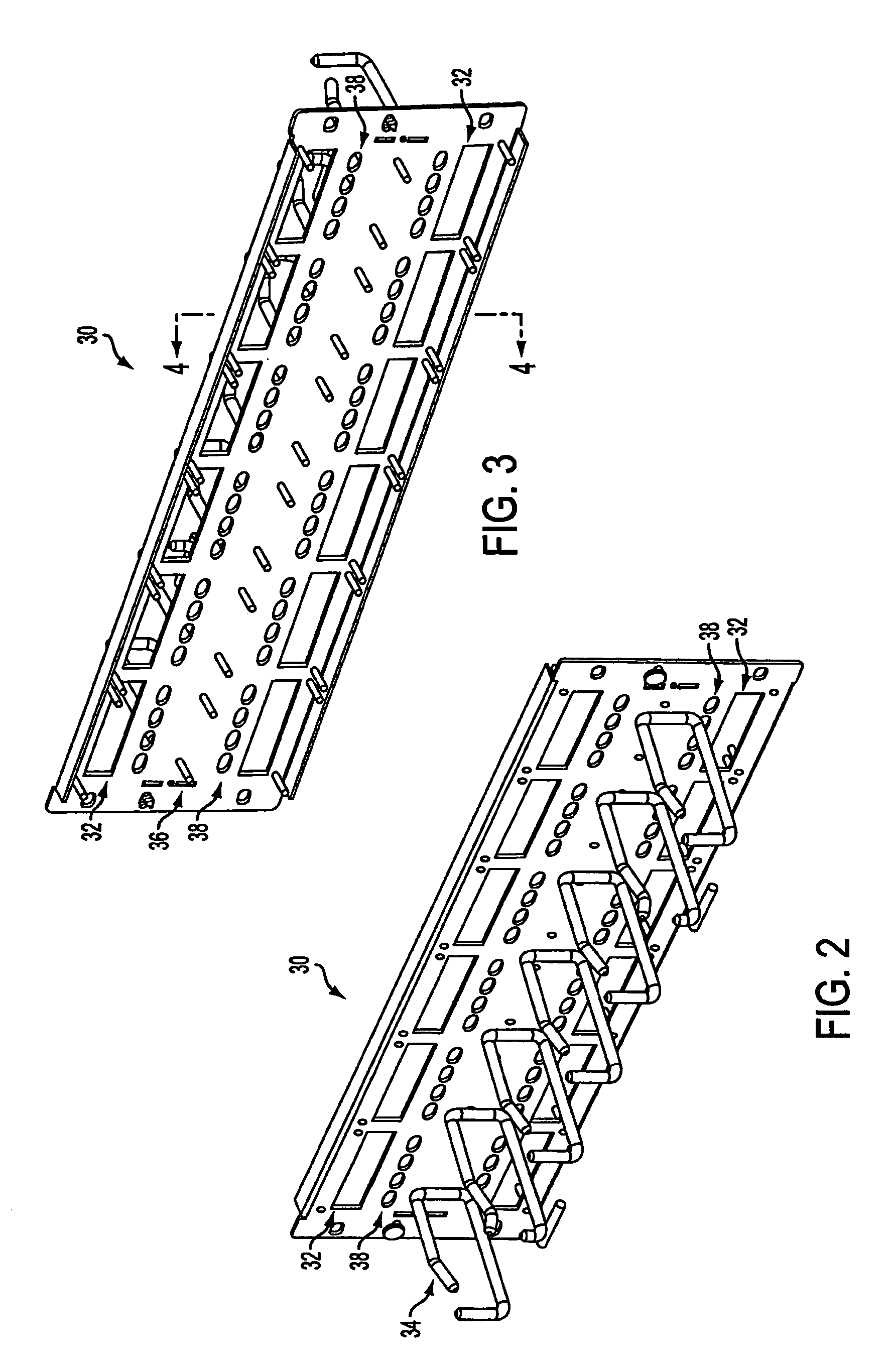
The present invention provides a system and method for an asset aware patch panel circuit that can include advanced feature components for use with asset management and security functions. The circuit can provide power and detection for remotely connected devices, and can be configured as a 3U panel with space for cable management and active circuitry between telecommunication circuits. The circuit includes a multilayered patch panel printed circuit board with compensating circuit elements to minimize the adverse effects of the active circuit. The circuit can support devices implementing techniques similar to those of IEEE802.3af and TIA-568B series, and can also provide data collection functions on various system parameters. The circuit provides at least category 3, 5, 5e, 6 and / or higher performance levels and is flexible to provide power to other proprietary device configurations, applications, or developing standards.

Problems solved by technology

Currently, limited progress has been made in such areas due to the impact of proposed improvements upon operational speed.
However, technicians often neglect to update the arrangement log each time a change is made.
To correct this, manual tracing of the patch cord must be performed which can be both time consuming and prone to further errors.
However, these methods require rather expensive sensing devices and are not very practical in all cases.
Any interruption between the communication link and the remote device, such as the removal of the device from the communication link, disrupts the circuit loop and triggers an alarm.
The detection, however, is limited to the mere absence or presence of a connector.
As disclosed in the Katzenberg patent, if no voltage drop is detected, then the remote equipment does not contain a DC resistive termination and this equipment is identified as unable to support remote power feed.
If a fixed voltage level is detected, the remote equipment contains a DC resistive termination, such as a “bob smith” termination and this equipment is also identified as being unable to support remote power feed.
The attempts to address device movement and detection, as well as attempts to address providing power to connected devices, typically fail to consider the communication performance degradation that such solutions can create.
Where attempts to correct performance degradation have been made, the solutions have typically been limited to the relocation and manipulation of signal traces.
Unfortunately, trace manipulation is not sufficient in every case to provide category 3, 5, 5e, 6 and / or higher and equivalent performance levels.
Although both the McCurdy and Hashim patents address crosstalk reductions at the connector position, each fails to address the performance degradation beyond the connector, including performance degradation that can be created due to additional active circuitry elements involved in providing advanced features.

Method used


Image

  • Midspan patch panel with compensation circuit for data terminal equipment, power insertion and data collection
  • Midspan patch panel with compensation circuit for data terminal equipment, power insertion and data collection
  • Midspan patch panel with compensation circuit for data terminal equipment, power insertion and data collection

Examples


Embodiment Construction

[0035]The present invention includes an electrical device which functions as a patch panel while providing additional advanced features. Where such features are provided, the present invention also serves to reduce or eliminate the adverse effects created by the additional feature electronics through positioning and separation of circuit elements, and / or providing effect minimizing or compensation circuit elements to increase performance levels.

[0036]The present invention can include one or more advanced feature components separately or in combination as either modular plug-in units or circuits disposed directly on the patch panel circuit board. As described in greater detail below, the advanced feature components can be used to detect devices attached to the patch panel cabling, both for security and to determine the device types with respect to power requirements, and further provide DC power to attached devices where practical. Power can be provided through techniques similar to ...


PUM


Abstract

A compensating advanced feature patch panel that can include removable modular or fixed electronic components located directly on the patch panel which are separately or in combination capable of providing advanced features such as device detection and power insertion. The patch panel provides communications between an insulation displacement connector (IDC) at a PD / User end, and any standard interface type using unshielded twisted pair cables, such as an RJ45 connector at a switch end at performance levels of at least category 3, 5, 5e, 6 and / or higher (e.g. 6e or 7) and equivalent performance levels as required by compensating for the active electronics used in providing advanced features through the use of inductive, capacitive and reactive circuit elements to compensate for advanced feature electronics.

Description

REFERENCE TO RELATED APPLICATIONS[0001]Related subject matter is disclosed in a U.S. patent application of AbuGhazaleh et al., entitled “Midspan Patch Panel With Circuit Separation For Data Terminal Equipment, Power Insertion And Data Collection”, Ser. No. 10 / 791,292 filed concurrently herewith and the subject matter of which is incorporated herein by reference.FIELD OF THE INVENTION[0002]The present invention relates to a patch panel replacement device including advanced features for providing power and data collection in association with attached network devices while providing at least category 3, 5, 5e, 6 and / or higher (e.g. 6e or 7) and equivalent performance levels as required. More particularly, the present invention relates to a patch panel printed circuit board including modular or fixed electrical components for use with providing advanced features and further including compensation circuit elements to minimize the adverse effects of electronics required for providing such...

Claims


Application Information

Patent Timeline
Patent Type & Authority Patents(United States)
IPC IPC(8): H05K7/06H01R24/00H05K1/00H05K1/02H05K1/16
CPCH05K1/0228H04Q1/13H05K1/0231H05K1/0298H05K2201/09236H05K2201/10189Y10S439/941H05K1/162H05K7/02H05K7/06
Inventor ABUGHAZALEH, SHADI A.BAXTER, ROBERT C.MAHMOOD, REHANMILLER, ALAN C.O'CONNOR, MICHAEL R.
Owner HUBBELL INC
Learn More