Packet flow control method and device

a technology of flow control and packaging, applied in data switching networks, frequency-division multiplexes, instruments, etc., can solve the problems of bandwidth waste, end-to-end network performance degradation, and increase in number

Inactive Publication Date: 2006-05-02
NOKIA SOLUTIONS & NETWORKS OY
View PDF9 Cites 29 Cited by
  • Summary
  • Abstract
  • Description
  • Claims
  • Application Information

AI Technical Summary

Benefits of technology

[0017]Accordingly, one channel is allowed to use extra memory after running out of its dynamically determined upper buffer memory limit (or quota), which helps to reduce packet-drops and thus improves the overall packet-throughput. Specifically, such a dynamic buffer sharing mechanism leads to an improved network throughput during congestions. Moreover, the traffic via the network device tends to be smoother and less bursty as a result of the dynamic buffer sharing which also leads to a higher buffer utilization.
[0020]According to another advantageous development, a channel with the longest packet queue may be selected as the first channel, and a predetermined data packet may be dropped from the queue of the first channel, when no free memory is available in the buffer memory. Thus, a packet of the longest queue is dropped to provide memory space for the new packet of the second channel. Hence, a push-out feature for fairness is provided with a longest-queue-drop mechanism. Preferably, the predetermined data packet to be dropped is located at the front of the queue of the first channel, to thereby provide an advantageous drop-from-front mechanism.
[0022]According to a further advantageous development, the channel with the longest packet queue may be determined by an estimation. Preferably, this estimation may be performed by storing the length and identity of the last determined longest queue, comparing the length of a current queue with the stored longest queue on a queuing event, and updating the length and identity of the stored longest queue according to the result of comparison. Such a longest-queue-drop policy counteracts an inherent unfairness obtained due to the tendency of connections to a round trip time (RTT) biasing.
[0025]Accordingly, packets with higher delay sensitivity can be allowed to be served on time from the buffer means, which results in a lower packet drop ratio, because more packets meet their deadlines and, hence, a higher system throughput and is suitable to support real time services. As long as the flow has traffic, it is guaranteed that the traffic on that flow can be transmitted at least at the nominal rate. Using this nominal rate model, a nominal rate is assigned per user flow. However, the model allows the service to be switched between different flows (even different packets) before reaching a service amount equal to the nominal rate. The overall service rate, however, for a given user would still meet the nominal rate. The residual rate can be “lent” to other flows to maximize total system throughput. Conversely, the current flow can “borrow” from the residual rates of other flows to smooth out peak rate demands which exceed its own nominal rate.
[0026]This nominal rate model leads to a far better control scheme that will provide fairness and guarantees the rate requirements for each flow because the nominal rate allocation is respected all the time. It is focussed on rate guarantees only. Therefore allowing the QoS scheduler to separate the delay allocation from the rate allocations, so no coupling may exist, and therefore improving resource utilization efficiency. The rate is controlled by the allocation of the nominal rate per user flow and by borrowing bandwidth from other flows in a controlled fashion. The delay can be controlled on a per-packet basis using a different model that integrates with the QoS scheduler.
[0027]Furthermore, arriving packets may be segmented into data segments and the packets may then be scheduled at the data segment level. This provides the capability for the QoS scheduler to switch service between packets. This way, packets with higher sensitivity do not have to wait until another packet transmission is complete if the packet being served can afford the extra delay. This leads to an increase in the system throughput.

Problems solved by technology

However, this underutilization of the buffer memory may lead to an increased number of packet-drops in case of traffic congestion and thus to an end-to-end network performance degradation.
For real time Variable Bit Rate (VBR) traffic (e.g. real-time conversational video), one of the problems to solve is to provide enough bandwidth to match the instantaneous rate demands, in order to meet the delay requirements of real-time traffic.
A straight forward solution is to assign a dedicated bandwidth to each flow, but if the flows have fluctuating instantaneous rates, such a solution leads to bandwidth waste (if the dedicated bandwidth is set to the peak rate demand) or lack of QoS guarantees (if the dedicated bandwidth is set lower).
A well-known solution is to use statistical multiplexing over multiple flows, but statistical multiplexing works well only over a large number of flows.
Over a cellular link, due to bandwidth and terminal limitations, it is not valid to assume a large number of flows.
The problem is considered an open problem.
However, some documented ideas have been proposed but only provide a partial solution to the problem.
For real time services support, lower bound delays are required, and given that the maximum delay is governed by the round duration, it would be impossible to provide different delay bounds to different flows as the number of user flows increases, therefore leading to a high packet drop ratio (packets exceeding their delay constraint are considered useless).
Given that the rate is fixed, the coupling between the rate allocation and the delay may lead to inefficient resource utilization (a low rate assignment reduce the QoS of the flow while a very large rate leads to a waste of bandwidth.
Even though this idea may meet the delay requirements under normal operations, it does not cope with congestion (this may be common for the real time traffic with variable rate characteristics such as video conferencing and video streaming).
In this scenario, packets with close deadlines will overbook the server, and given that there are no service rate control per user flow, the algorithm becomes unfair and packets will be dropped in an uncontrolled fashion.

Method used


Image

  • Packet flow control method and device
  • Packet flow control method and device
  • Packet flow control method and device

Examples


Embodiment Construction

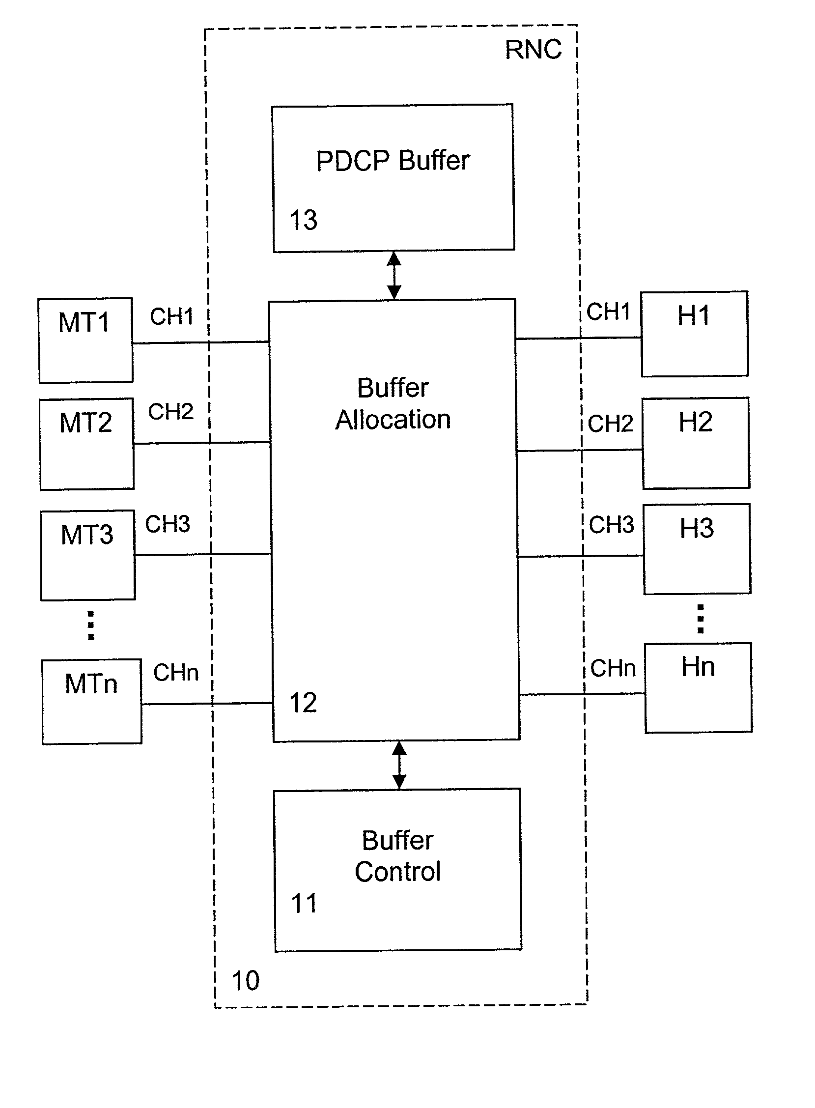
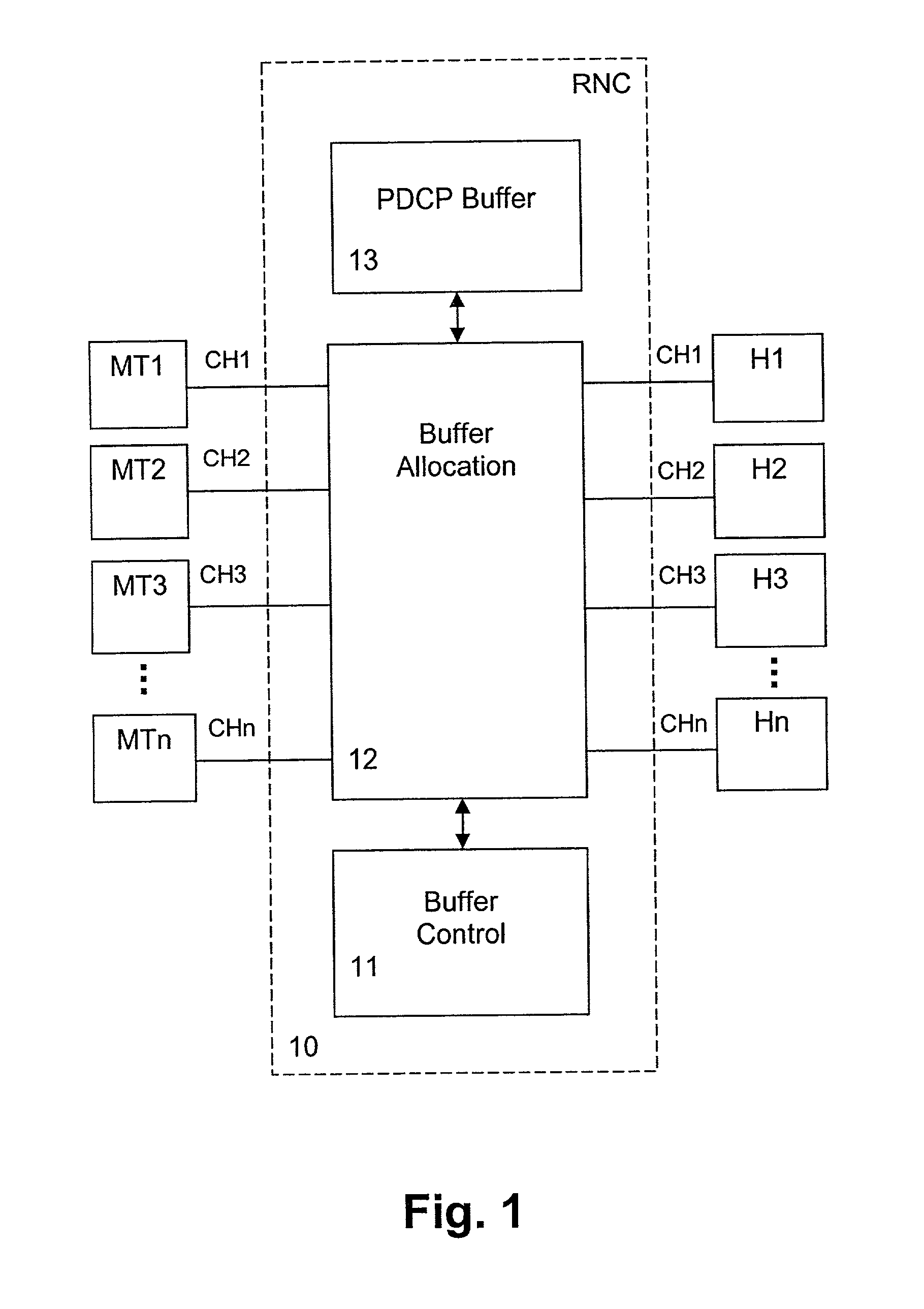
[0039]The preferred embodiments of the present invention will now be described on the basis of a PDCP layer queuing management and a MAC layer QoS scheduling function in a Radio Network Controller (RNC) 10 of a 3G network.

[0040]In FIG. 1, a functional block diagram of those RNC PDCP layer functions relevant to the first preferred embodiment of the present invention are shown. In particular, a buffer allocation unit or functionality 12 is used for optimizing packet flow control by sharing or allocating memory space of a PDCP buffer 13 between / to respective channels CH1 to CHn which are allocated to prevailing or active connections between respective mobile terminals MT1 to MTn and corresponding Internet hosts H1 to Hn. In a special case, data may also be exchanged between mobile terminals, such that an Internet host may actually correspond to another mobile terminal. In each allocated or reserved one of the channels CH1 to CHn, data packets (e.g. PDCP PDUs) may be stored in respectiv...


PUM


Abstract

The present invention relates to a method and network node for controlling packet flow in a buffer means (13; 14) of a network node of a data network, wherein a nominal capacity is assigned to each data flow, and an additional or free capacity is shifted from a first flow portion to a second flow portion when a new data packet of said second flow portion has been received and said nominal capacity has been exceeded. The nominal capacity may be an upper buffer memory limit used for controlling queuing of data packets in a buffer memory (13) of said buffer means, wherein the memory space of the buffer memory (13) is shared between a plurality of channels allocated to respective packet data connections. Then, the free capacity corresponds to a memory space shifted from a first channel to a second channel, when a new data packet of the second channel has been received and not enough memory space is available for the second channel. Thus, a dynamic buffer-sharing mechanism is provided which reduces the number of packet drops in the buffer memory (13) during congestion and improves network throughput. Alternatively, the nominal capacity may be a nominal flow rate at which data flow traffic is guaranteed in a QoS scheduling algorithm. Then, a residual rate corresponding to the difference between the nominal flow rate and an instantaneous traffic is shifted between flow portions of a buffer means controlled by the scheduling algorithm to maximize total system throughput.

Description

FIELD OF THE INVENTION[0001]The present invention relates to a method and network node for controlling packet flow in a buffer means of a network node of a data network, such as a 3G (3rd generation) mobile network, in particular using a Packet Data Convergence Protocol (PDCP) buffer in a PDCP layer or using a QoS scheduling algorithm in a Media Access Control (MAC) layer of.BACKGROUND OF THE INVENTION[0002]Network layer protocols are intended to be capable of operating over services derived from a wide variety of sub-networks and data links. UMTS (Universal Mobile Telecommunications System) supports several network layer protocols providing protocol transparency for the users of the service. Introduction of new network layer protocols to be transferred over the UMTS Terrestrial Radio Access Network (UTRAN) shall be possible without any changes to UTRAN protocols. Therefore, all functions related to transfer of packets from higher layers (PDCP Service Data Units (SDUs)) shall be car...

Claims


Application Information

Patent Timeline
Patent Type & Authority Patents(United States)
IPC IPC(8): H04L1/00H04L47/762H04W28/14H04W84/04
CPCH04L47/762H04W28/14H04L49/9084H04W28/08H04W72/12H04W84/04H04W28/0205H04W72/04
Inventor RUUTU, JUSSIZHANG, DONGMEISHICUNY, RENAUDMA, JLANLE, KHIEMNAIM, GHASSAN
Owner NOKIA SOLUTIONS & NETWORKS OY
Why Eureka
Try Eureka