Method of handoff at the border between CDMA underlay and overlay systems

a technology of overlay system and cdma, applied in the field of mobile communications, can solve the problems of affecting the reverse link of the adjacent carrier of the base station, the power of the uplink signal transmitted by the mobile terminal may be sufficiently large to interfere with the adjacent carrier's uplink signal, and the underlay base station to drop all ongoing calls

Active Publication Date: 2006-05-02
WSOU INVESTMENTS LLC +1
View PDF13 Cites 52 Cited by
  • Summary
  • Abstract
  • Description
  • Claims
  • Application Information

AI Technical Summary

Benefits of technology

[0008]In a second embodiment, the present invention is incorporated in a system in which the mobile terminal employs a single technology rather than the dual technology employed in the hybrid 1xEV / 3G-1X mobile terminal. In an embodiment in which multiple carrier are employed in different areas, a mobile terminal communicating with a base station at a carrier Fn used in an overlay area is determined to have the potential to cause interference with the reverse link of a base station that operates in an underlay area at an adjacent carrier Fn−1 when conditions similar to (1) and (2) above occur together. Specifically, this happens when together: (1) the measured power received at a mobile terminal from a base station in the underlay area that operates at adjacent carrier Fn−1 exceeds the measured power at the mobile terminal of the downlink signal received from the base station with which the mobile terminal is communicating on the carrier Fn by more than a first predetermined threshold that indicates that the mobile terminal is at the border of the overlay area; and (2) the measured power of the downlink signal received at the mobile terminal from the base station in the underlay area operating at carrier Fn−1 plus the power of the uplink signal currently being transmitted by the mobile terminal to the base station in the overlay area operating at carrier Fn is greater than a second predetermined threshold that indicates that the power of the signal received by the base station in the underlay area from the transmitting mobile terminal at carrier Fn can interfere with the operation of that base station. Unlike the situation with the hybrid 1xEV / 3G-1X mobile terminal in which the overlay 1xEV system does not communicate with the underlay 3G-1X system, in a single technology system these determinations would normally be implemented at the base station in the overlay area based on measurements made by the mobile terminals and reported back to the base station. Thus, when both of these conditions are met together, the base station issues a redirection order signaling the mobile terminal to switch its carrier, thereby handing off the mobile terminal to the base station in the underlay area. As in the first embodiment, pilot measurements and power averaging and / or extended measurement periods can be used for improved reliability in determining that both conditions are met and that a redirection order should be made.

Problems solved by technology

Adjacent channel interference, due to what is known as a “near-far” situation, has always been a problem in the multi-carrier deployment of CDMA mobile systems.
This near-far problem manifests itself at the border of an overlay area where additional CDMA carrier is deployed for capacity or other reasons.
When that carrier frequency is adjacent to a carrier frequency used by the base station in the underlay area that it is now near, the power of the uplink signal transmitted by the mobile terminal may be sufficiently large to interfere with that base station's reverse link on the adjacent carrier.
Specifically, due to the inability of the base station in the underlay area receiver to totally suppress adjacent channel signals, the magnitude of sideband of the uplink signal transmitted by the mobile terminal that is within an operating band of such an adjacent frequency carrier used by the base station in the underlay area, in a worst case scenario, can result in the total shut-down of that carrier by the underlay base station, causing that underlay base station to drop all ongoing calls and preventing customers from initiating and receiving new calls on that carrier.
Alternatively, but deleterious to service, the generated interference can shrink the second base station's coverage area and preclude that base station from providing service to mobile terminals in its coverage area.
The above-described near-far situation is likely to be a problem in CDMA systems when an additional carrier at a carrier frequency Fn is deployed as an overlay to alleviate capacity problems in underlay second or third generation (2G / 3G) mobile systems.
A general problem with these prior art solutions is that redirect and handoff was often triggered before the underlay base station to which the mobile terminal is being redirected could reliably handle the call, causing frequent dropped calls.
Specifically, the IS-856 1xEV standard does not support the redirection from 1xEV to 3G-1X while on a data call, nor does it provide any means to inform a mobile terminal about the underlay system when it is idle so that it can make an informed autonomous decision when to switch.
This creates a transition zone between the overlay 1xEV system and the underlay 3G-1X system, thereby wasting the capacity and the coverage of those 1xEV base stations on the border between the overlay and underlay system.
The 1xEV standard also supports an option to redirect individual mobile terminals to the underlay system, but there is lack of support for any MAHHO type of reporting about signal quality of the target 3G-1X carrier.
There is no reliable way, however, of determining whether or not a hybrid mobile terminal operating at the border and communicating with the overlay 1xEV system is likely to cause interference with a 3G-1X base station in the underlay area.
The potential for a deleterious impact on the underlay 3G-1X system therefore could seriously impact the deployment of a 1xEV system.

Method used


Image

  • Method of handoff at the border between CDMA underlay and overlay systems
  • Method of handoff at the border between CDMA underlay and overlay systems
  • Method of handoff at the border between CDMA underlay and overlay systems

Examples


Embodiment Construction

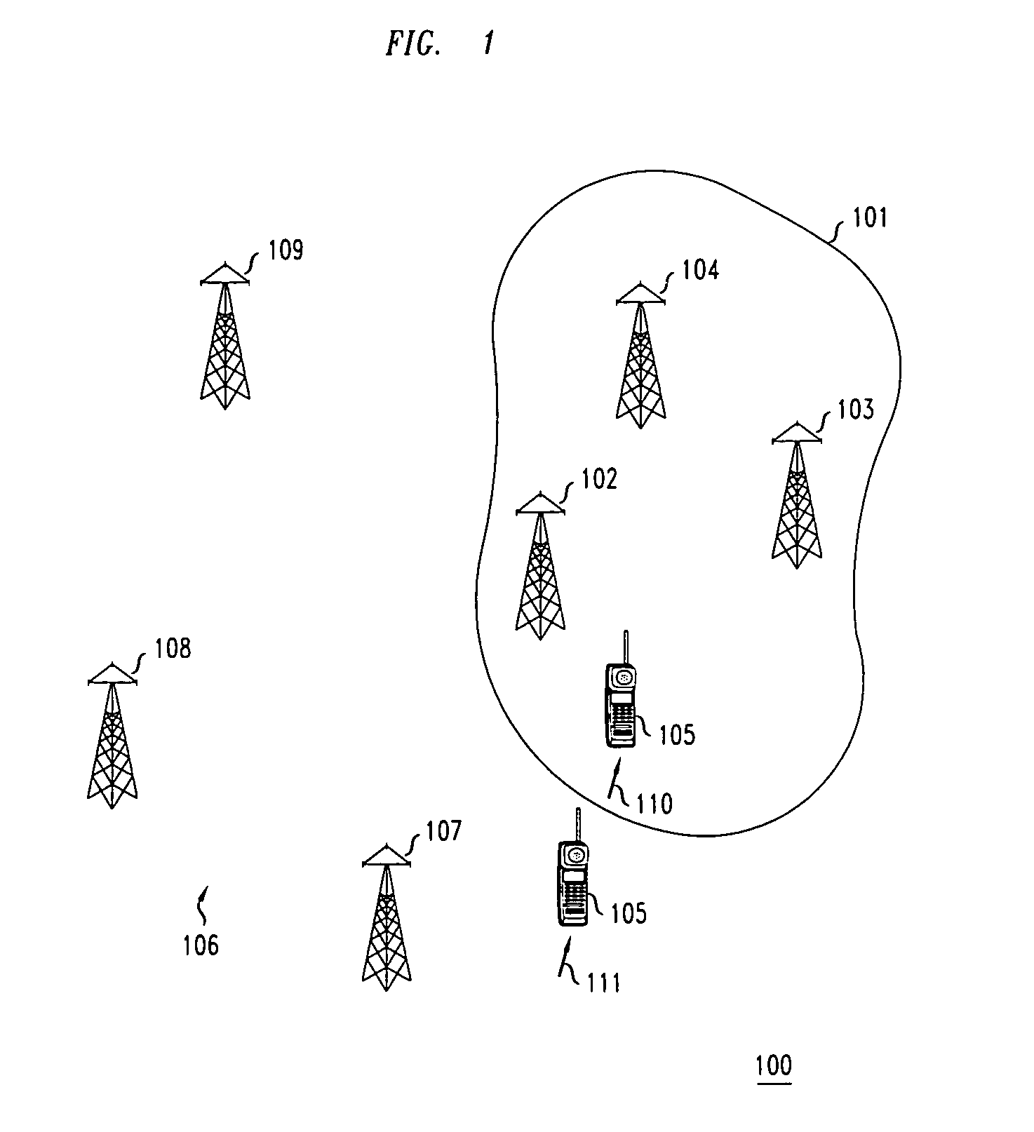
[0012]With reference to FIG. 1, a plurality of base stations are located within an overlay area 101 of a mobile service provider's area 100 consisting of the overlay area 101 and an underlay area 106. Although, for illustrative purposes, only three base stations 102, 103 and 104, are shown within overlay area 101, it should understood that a larger plurality of base stations would provide coverage to mobile subscribers within this area. In a described embodiment, the overlay area offers 1xEV high-speed data service to a user of a hybrid mobile terminal 105 that also functions as a 3G-1X mobile terminal. When operating in the latter mode, mobile terminal 105 provides voice and lower speed data service. Such a hybrid 1xEV / 3G-1X terminal 105 is capable of originating and receiving high-speed data calls through the base stations 102–104 when it is within the overlay area 101. Also, when it is within the overlay area 101, the hybrid mobile terminal 105, operating in its 3G-1X mode, is ca...


PUM


Abstract

To avoid interference with the reverse link of a base station within an underlay area, a described method determines when to redirect and handover a mobile terminal that is still communicating on an adjacent carrier with a border base station within an overlay area but is within the coverage area of the base station in the underlay area. The method determines that redirection and handover to the base station in the underlay area should occur when together: (1) the power being received on the downlink from the base station in the underlay area exceeds the power being received on the downlink from the border base station within the overlay area by a first predetermined threshold that indicates that the mobile terminal is at the border of the overlay area; and (2) the sum of the power being received on the downlink from the underlay base station plus the power of the signal being transmitted by the mobile terminal to the base station within the overlay area is greater than a second predetermined threshold that indicates that the power being received by the base station in the underlay area from the transmitting mobile terminal can interfere with the operation of that base station.

Description

TECHNICAL FIELD[0001]The present invention relates to mobile communications.BACKGROUND OF THE INVENTION[0002]Adjacent channel interference, due to what is known as a “near-far” situation, has always been a problem in the multi-carrier deployment of CDMA mobile systems. This near-far problem manifests itself at the border of an overlay area where additional CDMA carrier is deployed for capacity or other reasons. As a mobile terminal that is communicating with a border base station in the overlay area and operating at a carrier frequency deployed in that area moves across the border of the overlay area into the underlay area that is covered by base stations operating at other carrier frequencies, the mobile terminal is supposed to switch frequencies and be handed off to a second base station in the underlay area for continued communication at one of these other carrier frequencies, usually called a “hard” handoff. If, however, the mobile terminal doesn't switch on time, it is possible...

Claims


Application Information

Patent Timeline
Patent Type & Authority Patents(United States)
IPC IPC(8): H04Q7/36H04B7/26H04W36/04H04W36/20
CPCH04W36/04H04W36/20H01B7/0216H01B7/1825H05B3/56H05K9/0098
Inventor JOVANOVIC, VLADAN
Owner WSOU INVESTMENTS LLC
Why Eureka
Try Eureka