Method and apparatus for reading and controlling utility consumption

a utility consumption and method technology, applied in the direction of process and machine control, testing/monitoring control system, instruments, etc., can solve the problems of not being able to reliably not being able to effectively monitor and control power use, and not being able to view multiple devices or multiple locations by cohesive means

Inactive Publication Date: 2006-05-02
TRENDPOINT SYST
View PDF106 Cites 317 Cited by
  • Summary
  • Abstract
  • Description
  • Claims
  • Application Information

AI Technical Summary

Benefits of technology

[0012]In the present invention, if the calculated forecast indicates that the present usage rate will cause that consumer to exceed a predetermined target unit or cost level, a signal is provided by the computer to allow for the manual or automatic control of power-consuming devices to assure that the power use falls at or below the specified requirement. This is especially advantageous during energy crisis situations. A forecast rate for use may be shown as a red colored line graph. A second line, the baseline target consumption, may be displayed as a blue line graph. If a user is under their baseline target ...

Problems solved by technology

Such devices were typically developed as a cost saving method for the collection of data for electrical service providers but have provided little usability to the consumer.
In cases where consumers have been given some features through AMR systems, there has not been an ability to reliably monitor and control power use while maintaining a comfortable environment.
Further it provides no means cohesively view multiple devices or multiple locations.
However, no control means are shown as a way to reduce actual power cons...

Method used


Image

  • Method and apparatus for reading and controlling utility consumption
  • Method and apparatus for reading and controlling utility consumption
  • Method and apparatus for reading and controlling utility consumption

Examples


Embodiment Construction

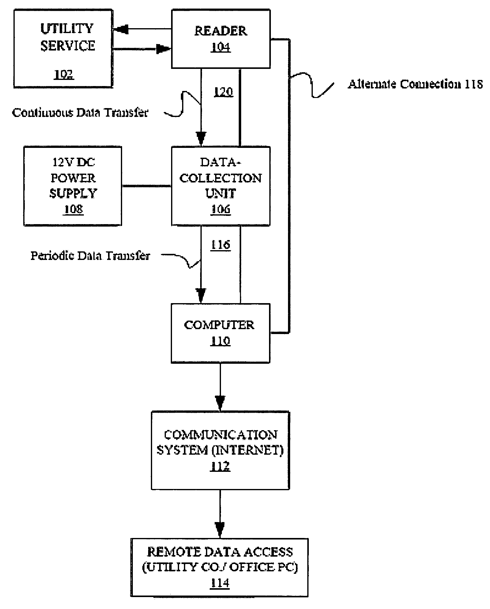
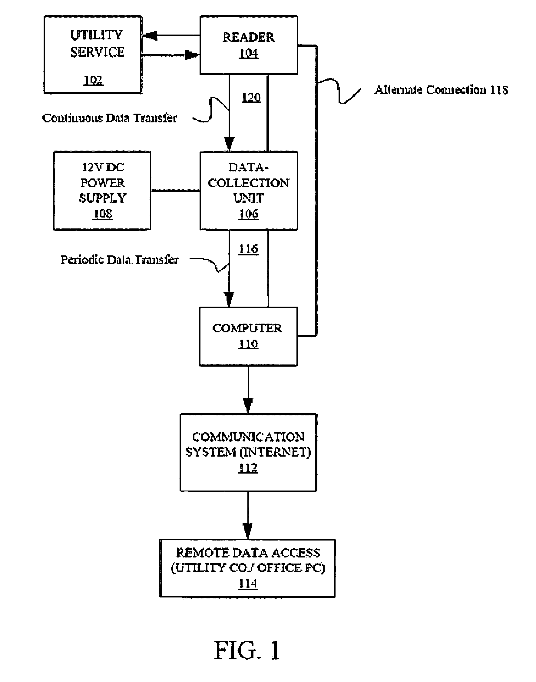
[0022]FIG. 1 illustrates a block schematic diagram of an apparatus 100′ for reading and managing power consumption in accordance with the present invention. As shown in FIG. 1, a reader 104 is attached to a typical utility service point, 102 such as an electrical panel commonly found on homes, apartment buildings and commercial buildings. The reader 104 provides a means for automatically reading power. The data generated by the reader 104 may be continuously transferred through a connection such as a serial cable 120, to a data collection unit 106 or alternatively directly to the monitoring device 110, such as a computer.

[0023]The data collector 106 is therefore optional. When provided, the data collection unit stores data generated by the reader 104. The data collection unit 106 may store data for a limited time when the monitoring device (computer) 110 is shut off or in the event of a power failure. With appropriate memory, the unit 106 may be able to store data for up to a year. ...


PUM


Abstract

A method and system for controlling electric power consumption using a computer to create a forecast and then controlling devices that use power based on the forecast. An automatic reader device is used to gather power consumption data from a point of utility service. The power consumption data is then provided to a computer. The computer is used to create a forecast of energy use for instantaneous demand and time-based usage. The computer then provides alerts based on the forecast for the manual or automatic control of devices that consume electricity. The system may be managed locally or remotely by a computer, PDA, cell phone or other network enabled device.

Description

[0001]This application is a continuation-in-part of prior application Ser. No. 10 / 615,572, filed Jul. 8, 2003, which is a continuation-in-part of application Ser. No. 09 / 896,159, filed Jun. 28, 2001, now U.S. Pat. No. 6,622,097. The entire contents of application Ser. No. 10 / 615,572 and of U.S. Pat. No. 6,622,097 are hereby incorporated by reference.BACKGROUND OF THE INVENTION[0002]There are various types of electrical power monitoring devices on the market today. These include a number of units which operate as an automatic meter reading (AMR) device or which work in conjunction with an AMR device. Such devices were typically developed as a cost saving method for the collection of data for electrical service providers but have provided little usability to the consumer. In cases where consumers have been given some features through AMR systems, there has not been an ability to reliably monitor and control power use while maintaining a comfortable environment.[0003]Controlling the am...

Claims


Application Information

Patent Timeline
IPC IPC(8): G01R21/06G01R21/133
CPCG01R21/133
Inventor HUNTER, ROBERT R.
Owner TRENDPOINT SYST
Why Eureka
Try Eureka