
Instruction cache association crossbar switch

a crossbar switch and instruction technology, applied in the direction of digital computers, instruments, computing, etc., can solve the problems of reducing the switching voltage of the instruction execution rate, requiring extra surface area, and slowing the system speed, so as to reduce the switching voltage, simplify the circuitry, and reduce the power

Inactive Publication Date: 2006-05-02
INTERGRAPH
View PDF138 Cites 5 Cited by
  • Summary
  • Abstract
  • Description
  • Claims
  • Application Information

AI Technical Summary

Benefits of technology

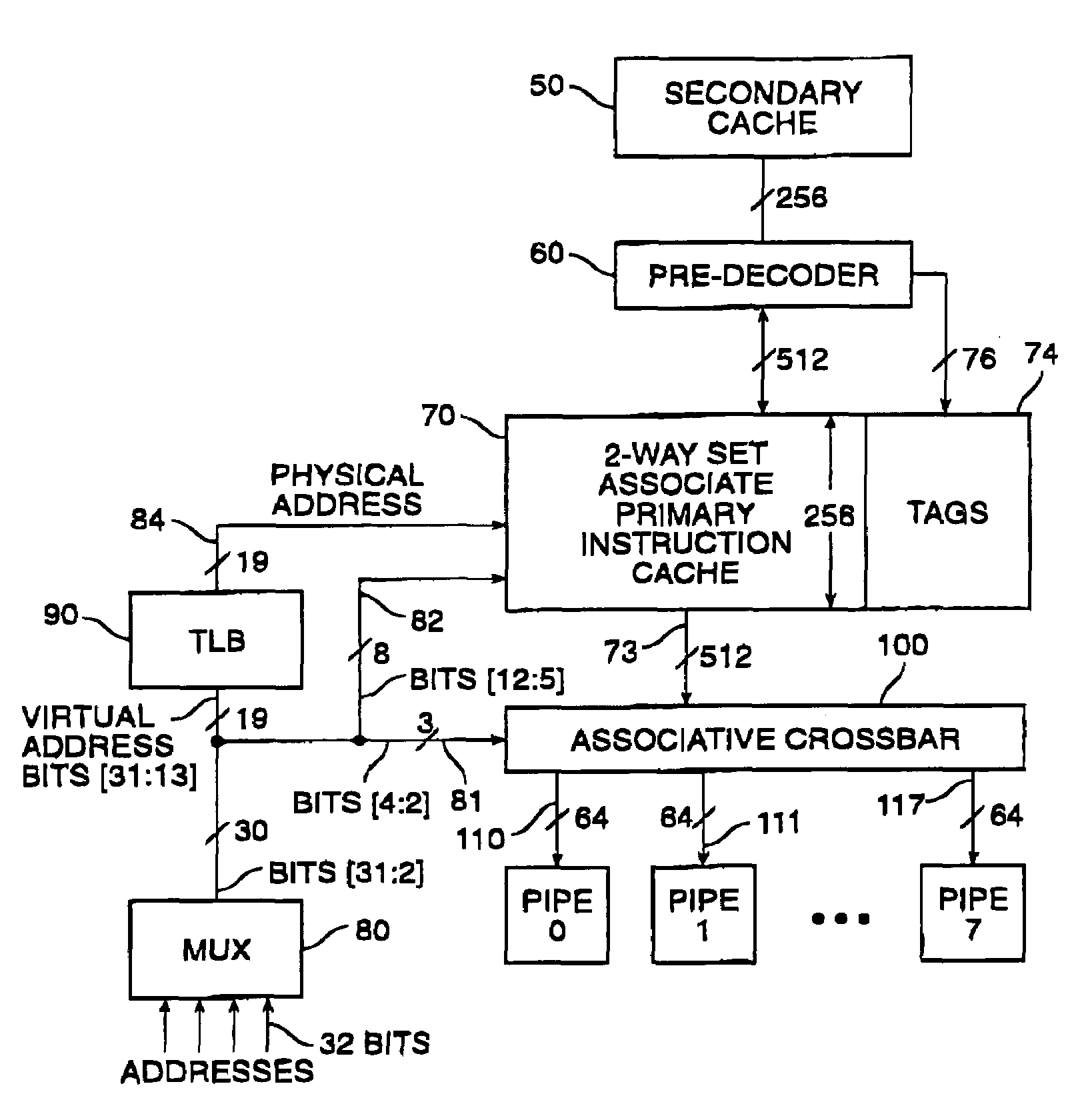
[0017]We have developed a computing system architecture that enables instructions to be routed to an appropriate pipeline more quickly, at lower power, and with simpler circuitry than previously possible. This invention places the crossbar switch earlier in the pipeline, making it a part of the initial instruction fetch operation. This allows the crossbar to be a part of the cache itself, rather than a stage in the instruction pipeline. It also allows the crossbar to take advantage of circuit design parameters that are typical of regular memory structures rather than random logic. Such advantages include: lower switching voltages (200–300 milliamps rather than 3–5 volts); more compact design, and higher switching speeds. In addition, if the crossbar is placed in the cache, the need for many sense amplifiers is eliminated, reducing the circuitry required in the system as a whole.
[0020]In a preferred embodiment of this invention the associative crossbar is implemented in the instruction cache. By placing the crossbar in the cache all switching is done at low signal levels (approximately 200–300 millivolts). Switching at these low levels is substantially faster than switching at higher levels (5 volts) after the sense amplifiers. The lower power also eliminates the need for large driver circuits, and eliminates numerous sense amplifiers. Additionally by implementing the crossbar in the cache, the layout pitch of the crossbar lines matches the pitch of the layout of the cache.

Problems solved by technology

Unfortunately, decoding in this manner slows system speed and requires extra surface area on the integrated circuit upon which the processor is formed.
Thus, in these approaches, the instruction execution rate is limited to the clock speed for the system.
There is a high hardware overhead associated with this hardware instruction scheduling process.
Thus for much of the execution time, most of the instruction bandwidth and the instruction memory are unused.
There is often a very limited amount of parallelism available in a randomly chosen sequence of instructions, especially if the functional units are pipelined.
Another disadvantage of VLIW architectures which results from the fixed number of slots in the very long instruction word for classes of instructions, is that a typical VLIW instruction will contain information in only a few of its fields.
This is inefficient, requiring the system to be designed for a circumstance that occurs only rarely—a fully populated instruction word.
Another disadvantage of VLIW systems is the need to increase the amount of code.
In short, VLIW machines tend to be wasteful of memory space and memory bandwidth except for only a very limited class of programs.

Method used


Image

  • Instruction cache association crossbar switch
  • Instruction cache association crossbar switch
  • Instruction cache association crossbar switch

Examples


Embodiment Construction

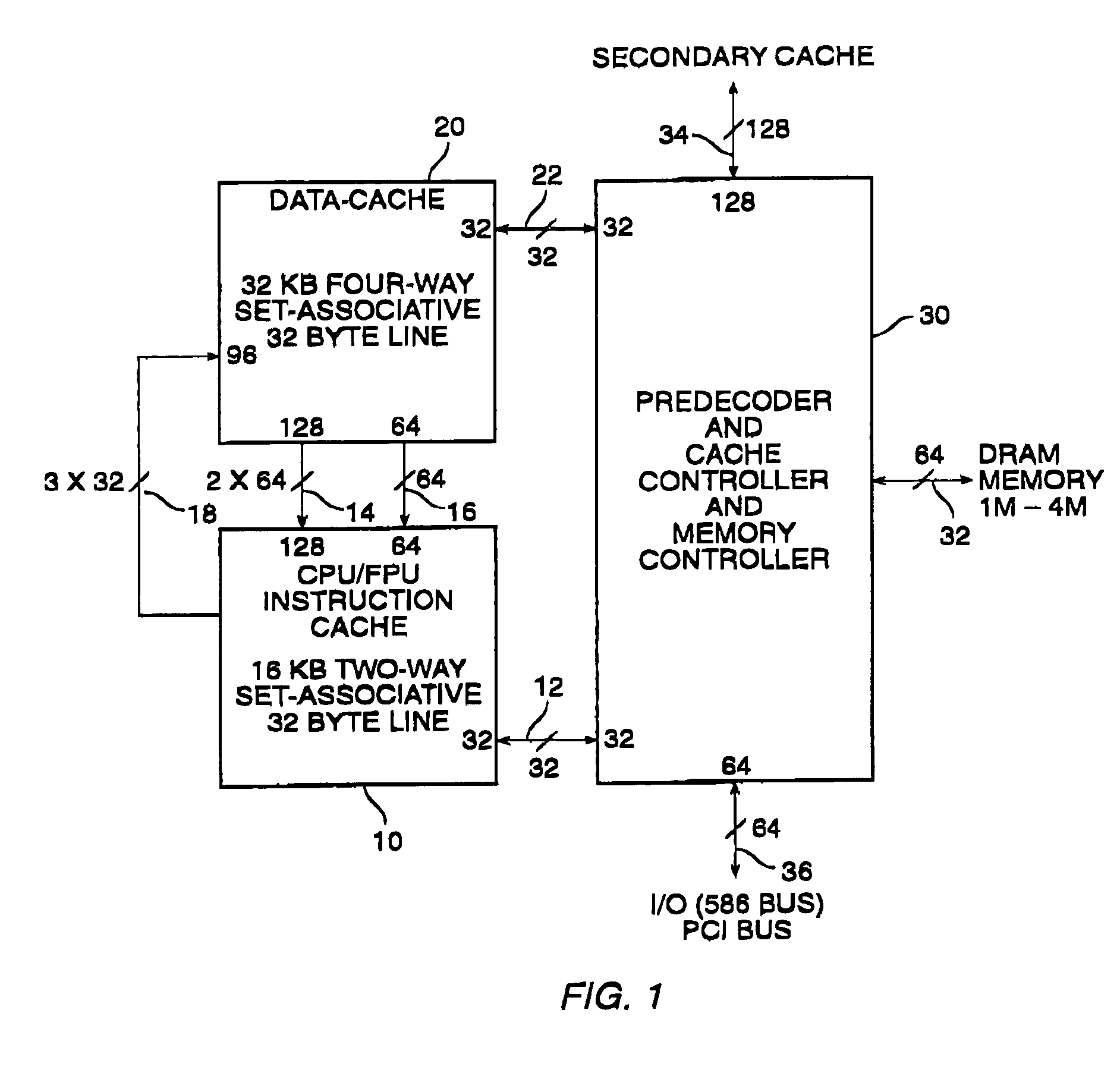
[0044]FIG. 1 is a block diagram of a computer system incorporating the associative crossbar switch according to the preferred embodiment of this invention. The following briefly describes the overall preferred system environment within which the crossbar is incorporated. For additional information about the system, see copending U.S. patent application Ser. No. 08 / 147,800, filed Nov. 5, 1993, and entitled “Software Scheduled Superscaler Computer Architecture,” which is incorporated by reference herein. FIG. 1 illustrates the organization of the integrated circuit chips by which the computing system is formed. As depicted, the system includes a first integrated circuit 10 that includes a central processing unit, a floating point unit, and an instruction cache.

[0045]In the preferred embodiment the instruction cache is a 16 kilobyte two-way set-associative 32 byte line cache. A set associative cache is one in which the lines (or blocks) can be placed only in a restricted set of locatio...


PUM


Abstract

A computing system as described in which individual instructions are executable in parallel by processing pipelines, and instructions to be executed in parallel by different pipelines are supplied to the pipelines simultaneously. The system includes storage for storing an arbitrary number of the instructions to be executed. The instructions to be executed are tagged with pipeline identification tags indicative of the pipeline to which they should be dispatched. The pipeline identification tags are supplied to a system which controls a crossbar switch, enabling the tags to be used to control the switch and supply the appropriate instructions simultaneously to the differing pipelines.

Description

CROSS REFERENCE TO RELATED APPLICATIONS[0001]This is a continuation of U.S. application Ser. No. 09 / 057,861 filed Apr. 9, 1998, U.S. Pat. No. 6,892,293 which is continuation of U.S. application Ser. No. 08 / 754,337 filed Nov. 22, 1996, now U.S. Pat. No. 5,794,003; which is a continuation of U.S. application Ser. No. 08 / 498,135, filed Jul. 5, 1995, now abandoned, which is a continuation of U.S. application Ser. No. 08 / 147,797 filed Nov. 5, 1993, now abandoned.BACKGROUND OF THE INVENTION[0002]This invention relates to the architecture of computing systems, and in particular to an architecture in which individual instructions may be executed in parallel, as well as to methods and apparatus for accomplishing that.[0003]A common goal in the design of computer architectures is to increase the speed of execution of a given set of instructions. One approach to increasing instruction execution rates is to issue more than one instruction per clock cycle, in other words, to issue instructions i...

Claims


Application Information

Patent Timeline
Patent Type & Authority Patents(United States)
IPC IPC(8): G06F9/30G06F9/38
CPCG06F9/3802G06F9/3814G06F9/3885G06F9/3853G06F9/382
Inventor SACHS, HOWARD G.ARYA, SIAMAK
Owner INTERGRAPH
Learn More