Vacuum packaging apparatus and method

Inactive Publication Date: 2006-05-09
ULTRASOURCE
View PDF8 Cites 9 Cited by
  • Summary
  • Abstract
  • Description
  • Claims
  • Application Information

AI Technical Summary

Benefits of technology

[0020]The user then closes the lid and a slight vacuum is drawn to seal the lid tightly against the base. With the bar unheated, the combined cutting mechanism and heating bar is then lowered, via the actuator, to cut spaced slits across a portion of the bag, leaving uncut sections of the bag. Leaving sections of uncut bag on either side of the bag prevents the pouch trim from tearing both during the vacuum packaging process and thereafter. The cutting and heating mechanism is then retracted.
[0021]The vacuum device then evacuates the air in the bag, compressing the conte

Problems solved by technology

Also, it is sometimes either expensive to package a product in a box or desirable to visibly display the product.
This packaging arrangement suffers the drawback that the entire bag must be located in the cavity in order to evacuate the air therein.
This bag material increases the total size of the package, and is visually unappealing.
Furthermore, this type of machine is not well suited to package large items by reducing the size of the items by pulling a vacuum through the package.
This system would tear the pouch completely loose during the initial vacuum draw down and disrupt the packaging cycle.
Like the vacuum packaging machine

Method used


Image

  • Vacuum packaging apparatus and method
  • Vacuum packaging apparatus and method
  • Vacuum packaging apparatus and method

Examples


Example

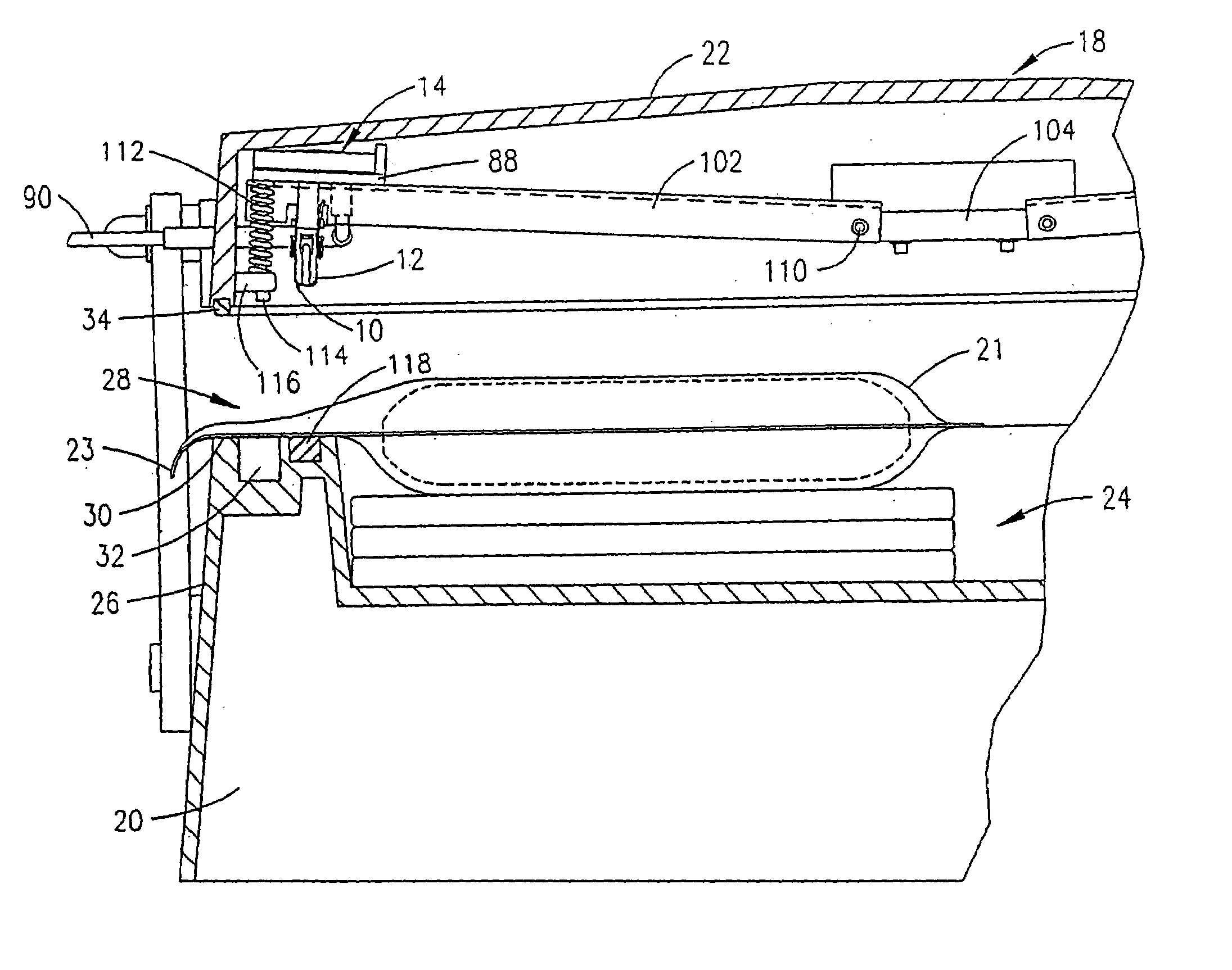
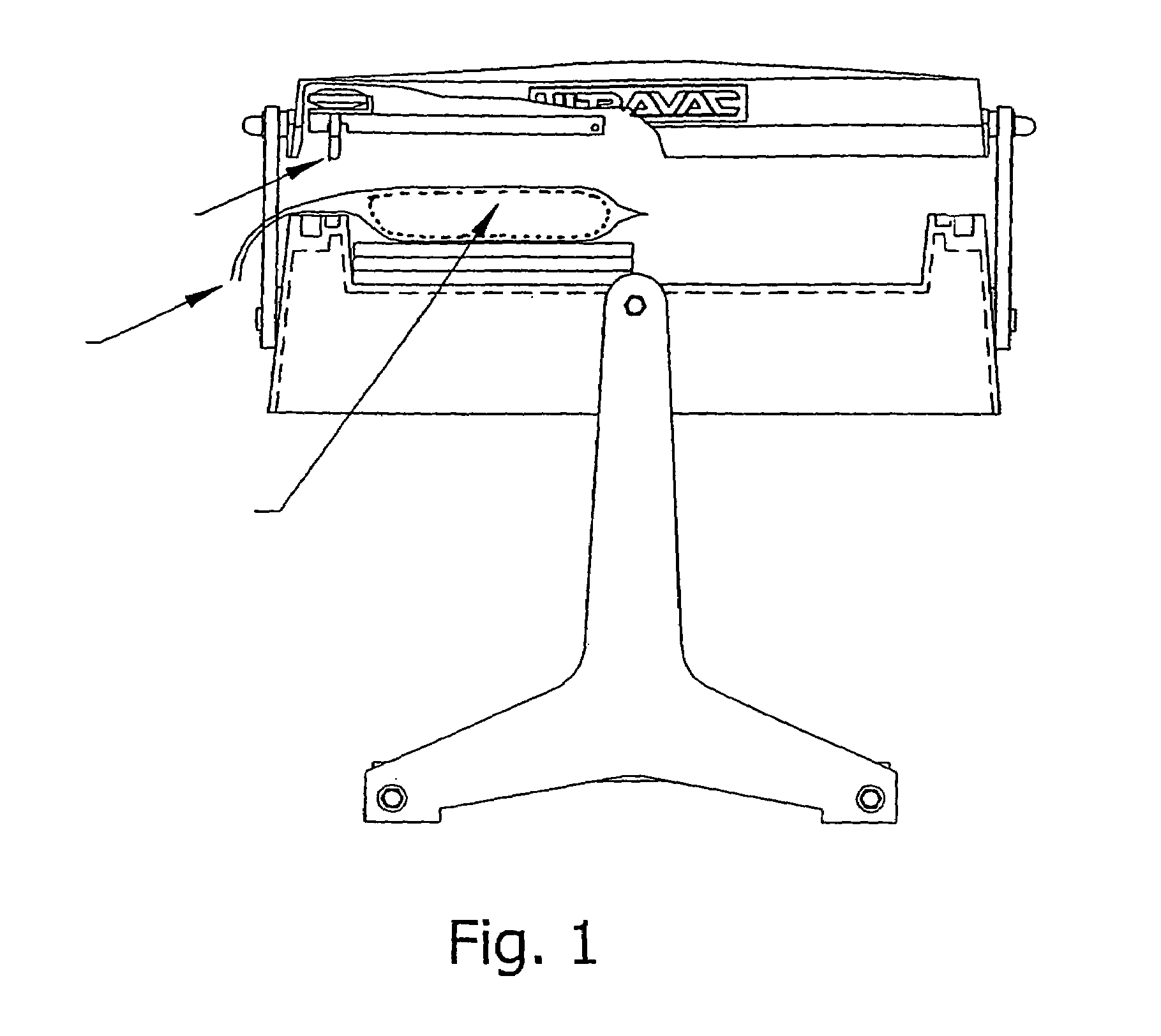
[0034]As illustrated by FIG. 1, the present invention is a vacuum packaging machine 18 that is designed to vacuum pack products that are not subject to reduction, such as food products, as well as items that are subject to reduction through vacuum packaging, such as clothing, outdoor wear, sleeping bags, other fabric derived products and other flexible, resilient compressible materials.

[0035]As illustrated by FIGS. 1 and 4–10, the vacuum packaging machine 18 of the present invention generally comprises a base 20, having a cavity 24 located therein, and a lid 22 that seals over the cavity 24 of the base 20. The cavity 24 is formed within an upstanding wall 26 of the base, the cavity having an open top end 28. The wall 26 has a flat top surface 30. At least a portion of the wall 26 includes a slot 32 in which a portion of a packaging bag 21 may be positioned.

[0036]The lid 22 has a mating surface for engagement with the top surface 30 of the wall 26 of the base 20, the lid 22 designed ...


PUM

PropertyMeasurementUnit
Lengthaaaaaaaaaa
Areaaaaaaaaaaa

Abstract

A combined cutting blade and heat bar for use with a vacuum packaging device having a lid for sealing over the cavity of a base is disclosed. The cutting blade and heat bar are connected to one another and movable via a single actuating mechanism mounted to the lid. In use, in one step the combined mechanism is lowered with the heat bar unheated and the cutting element cuts slits in the bag for evacuation of the air. After air evacuation, the combined mechanism is lowered with the heat bar heated, melting the bag closed behind the slitted area of the bag.

Description

[0001]This application is a Continuation of application Ser. No. 10 / 085,447, filed Feb. 28, 2002, now abandoned.BACKGROUND OF THE INVENTION[0002]A. Field of the Invention[0003]The present invention relates to a mechanism for use with a vacuum packaging apparatus. More particularly, the invention is a combined cutting blade and heating bar for use in cutting and sealing vacuum packing bags, and in particular, oversized compressible content in vacuum packing bags.[0004]B. Description of the Related Art[0005]Manufacturers often desire to package their products in air-tight or shrinked wrapped bags. For example, a manufacturer may wish to seal a food product in an air-tight package to ensure its freshness or may wish to vacuum pack a compressible product in order to reduce the size of the packaging. Also, it is sometimes either expensive to package a product in a box or desirable to visibly display the product. In these cases, the manufacturer may shrink-wrap the product in a clear plas...

Claims


Application Information

Patent Timeline
IPC IPC(8): B65B31/00B65B31/02
CPCB29C65/743B29C66/81431B29C66/00145B29C66/0044B29C66/1122B29C66/43121B29C66/81457B29C66/8161B29C66/82421B29C66/8324B65B31/024B29C65/226B29C65/222B29C65/228B29C65/229B29C65/7437B29C66/872B29C65/7451B29C66/8221B29C66/8227B29C66/849
Inventor KNOWLTON, SCOTTGROVE, TIMOTHY A.
Owner ULTRASOURCE
Why Eureka
Try Eureka