
Soil or snow probe

a probe and snow technology, applied in the field of probes, can solve the problems of increasing the occurrence of fatalities, taking about 35 minutes, and not providing a cross-slope profile, so as to improve the portability of the probe, save the cost of components, and improve the sensitivity

Inactive Publication Date: 2006-05-09
HIMACHAL SAFETY SYST
View PDF8 Cites 22 Cited by
  • Summary
  • Abstract
  • Description
  • Claims
  • Application Information

AI Technical Summary

Benefits of technology

[0015]By positioning the sensor unit in the head and not at the end of the shaft as proposed in U.S. Pat. No. 5,831,161 noise from the vibration of the drive shaft is eliminated and makes interpretation of the sensor signals easier.
[0016]An important advantage derived from the use of the accelerometer is the ability to manually insert the probe into soil or snow. The manual insertion results in acceleration and velocity changes from which the distance travelled can be calculated knowing the time taken. The distance traveled gives the depth of snow and by correlating the resistance to penetration with time the resistance at different depths can be calculated and graphed.
[0017]This invention is partly predicated on the discovery that using a low duro polymer in the load cell reduces the interference of external noise in the load cell signals.
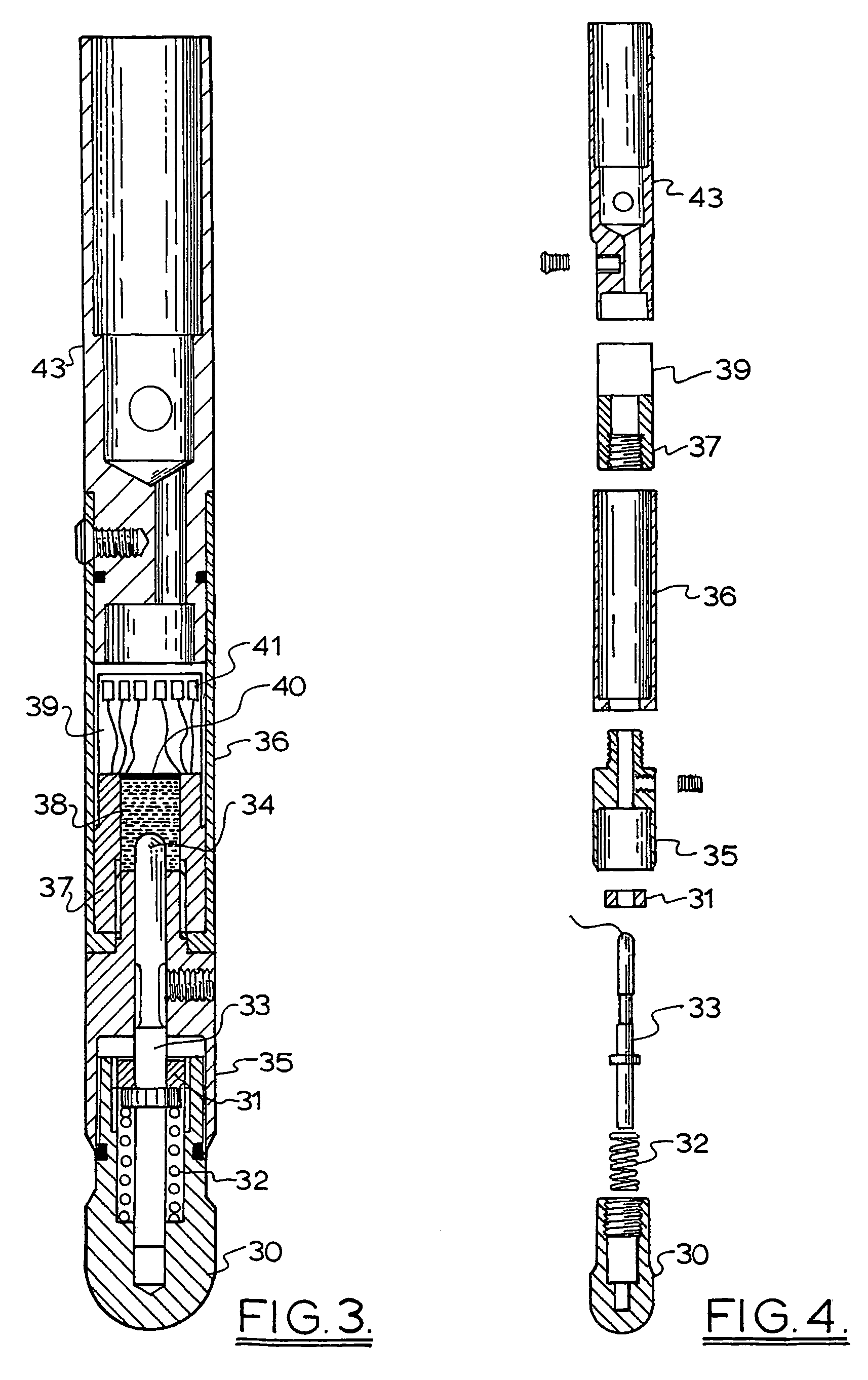
[0022]The low duro polymer preferably has a low shore hardness of 5 to 30 more preferably 8–10 and may be selected from rubber like materials preferably with linear compression gradients such as natural and synthetic rubbers, polyurethanes and preferably silicone polymers such as those sold by Dow Corning. It is preferred that the material has a low coefficient of thermal expansion, low shear strength, a high bulk modulus and remains flexible at low temperatures. The selected low duro polymers provide an hydraulic advantage with low hysteresis.
[0025]The use of an accelerometer eliminates the need for the head to have a constant velocity and enables the head to be manually driven in the soil or snow and does away with the need for a constant velocity penetrometer which requires a tripod, a motor and a drive shaft. This saves component cost and improves the portability of the probe. The accelerometer may be part of the sensing unit or a separate unit in the head or may be at any point on the probe shaft to which the head is attached as long as its movement parallels the movement of the head.
[0040]This enables a slope to be assessed for avalanche risk in a very short time. Preferably the measurements are made at several points in line across a contour of the slope and several such lines down the slope are measured and analysed. Alternatively lines of points down the slope may be measured. The points are preferably 10 to 15 meters apart and the contour lines are 50 to 75 meters apart. The best sections of a slope to take points on are adjacent convex rolls as experience shows that these are more likely sites for avalanches.

Problems solved by technology

Recent years have seen an increase in the occurrence of fatalities.
This takes about 35 minutes and does not provide a cross-slope profile of a slope unless several snow pits are dug.
The snow penetrometers discussed above do not provide a measure that can be used to predict the likelihood of an avalanche.

Method used


Image

  • Soil or snow probe
  • Soil or snow probe
  • Soil or snow probe

Examples


Embodiment Construction

[0053]The snow probe equipment required for the present invention is a probe head containing the sensors attached to a collapsible shaft up to 5 meters in length with a portable control box containing the programmed controller and processor and a display screen or printer for displaying the output.

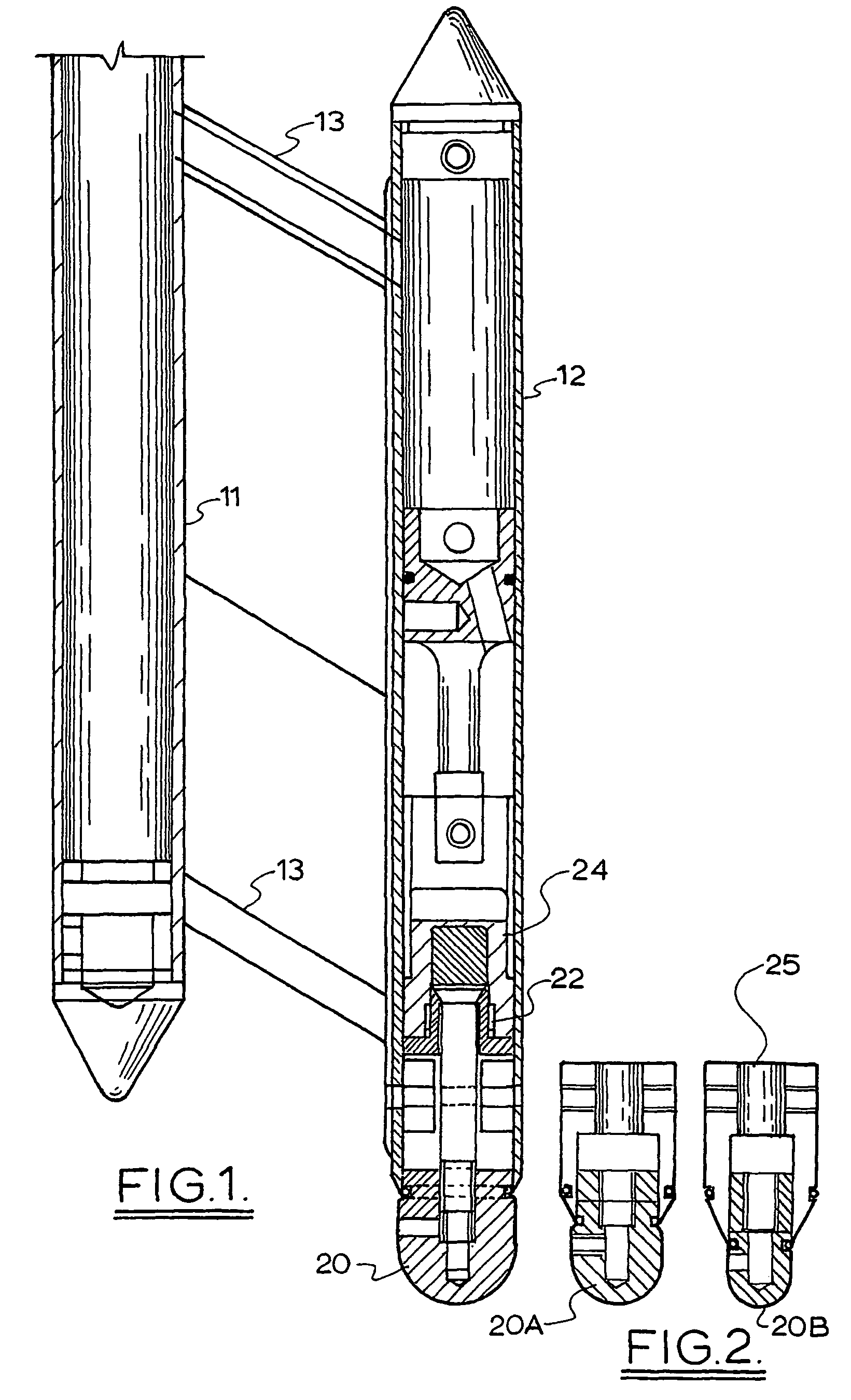
[0054]As shown in FIG. 1 the probe has a central shaft 11 and 3 sensor tubes 12 equally spaced from each other and the central shaft 11.

[0055]The sensor tubes 12 are rigidly attached to the shaft 11 by way of the struts 13.

[0056]At the lower end of each sensor tube 12 is a penetrator head 20 which is of a predetermined diameter. Each of the 3 heads 20 is of varying diameter up to a diameter equal or greater to the diameter of the sensor tube 12. Each penetrator head, 20 in FIG. 1 and 20A and 20B in FIG. 2, is domed to present a shaped surface to provide an optimum resistance to penetration. Each penetrating head 20, 20A or 20B is mounted on a piston 22 that is mounted within the sensor tub...


PUM

PropertyMeasurementUnit
shore hardnessaaaaaaaaaa
lengthaaaaaaaaaa

Abstract

A soil or snow probe which incorporates a load cell in the probe head and also an accelerometer so that a vertical strength profile of the snow or soil can be established. The device does not need to be driven at a constant speed and can be manually driven into the soil or snow. The resistance to penetration is measured using a load cell which incorporates a low duro polymer selected for its ability to behave like a non compressible fluid. The device is portable and provides data quickly.

Description

FIELD OF THE INVENTION[0001]This invention relates to probes for measuring density and strength characteristics of soil or snow.BACKGROUND TO THE INVENTION[0002]Soil or snow strength characteristics in vertical plane are important in determining load bearing capacity and in snow characterisations of the snow layers is important in predicting the likelihood of avalanches.[0003]U.S. Pat. No. 4,806,153 discloses a soil penetrometer incorporating sensors to measure penetration resistance and pore water pressure and a recording and control unit to store the sensor readings for transfer to an above ground computer for analysis.[0004]U.S. Pat. No. 6,062,090 discloses a method and penetrometer for measuring as a function of time the resistance to penetration of a soil bed for evaluating highway and railroad bed surfaces.[0005]Since the middle of the century there have been several hundred documented fatal avalanche accidents claiming hundreds of lives. Recent years have seen an increase in ...

Claims


Application Information

Patent Timeline
Patent Type & Authority Patents(United States)
IPC IPC(8): G01N3/00G01N3/32G01N3/42E02D1/00E02D1/02G01L1/00G01L5/00G01N3/06G01N3/30G01N3/48
CPCE02D1/022G01N3/42G01N2203/0682G01N33/24
Inventor MACKENZIE, RODERICKPAYTEN, WARWICK
Owner HIMACHAL SAFETY SYST
Learn More