Circulation member of ball screw and ball screw using same

a technology of circular member and ball screw, which is applied in the direction of gearing, washers, hoisting equipment, etc., can solve the problems of further difficulty in working, high manufacturing cost, and difficulty in bending the tube with predetermined dimensional performance, so as to achieve the effect of convenient manufacturing

Inactive Publication Date: 2006-05-09
THK CO LTD
View PDF9 Cites 31 Cited by
  • Summary
  • Abstract
  • Description
  • Claims
  • Application Information

AI Technical Summary

Benefits of technology

[0010]The object of the present invention is to provide a circulation member of a ball screw capable of being easily manufactured even if a pair of leg portions provided at both end portions of a

Problems solved by technology

In this known method, however, much manufacturing cost is involved and it is difficult to bend the tube with predetermined dimensional performance, providing a problem.
Especially, when it is required to incline the leg portions 3b, 3b of the return pipe 3 in the directions different fr

Method used


Image

  • Circulation member of ball screw and ball screw using same
  • Circulation member of ball screw and ball screw using same
  • Circulation member of ball screw and ball screw using same

Examples


Embodiment Construction

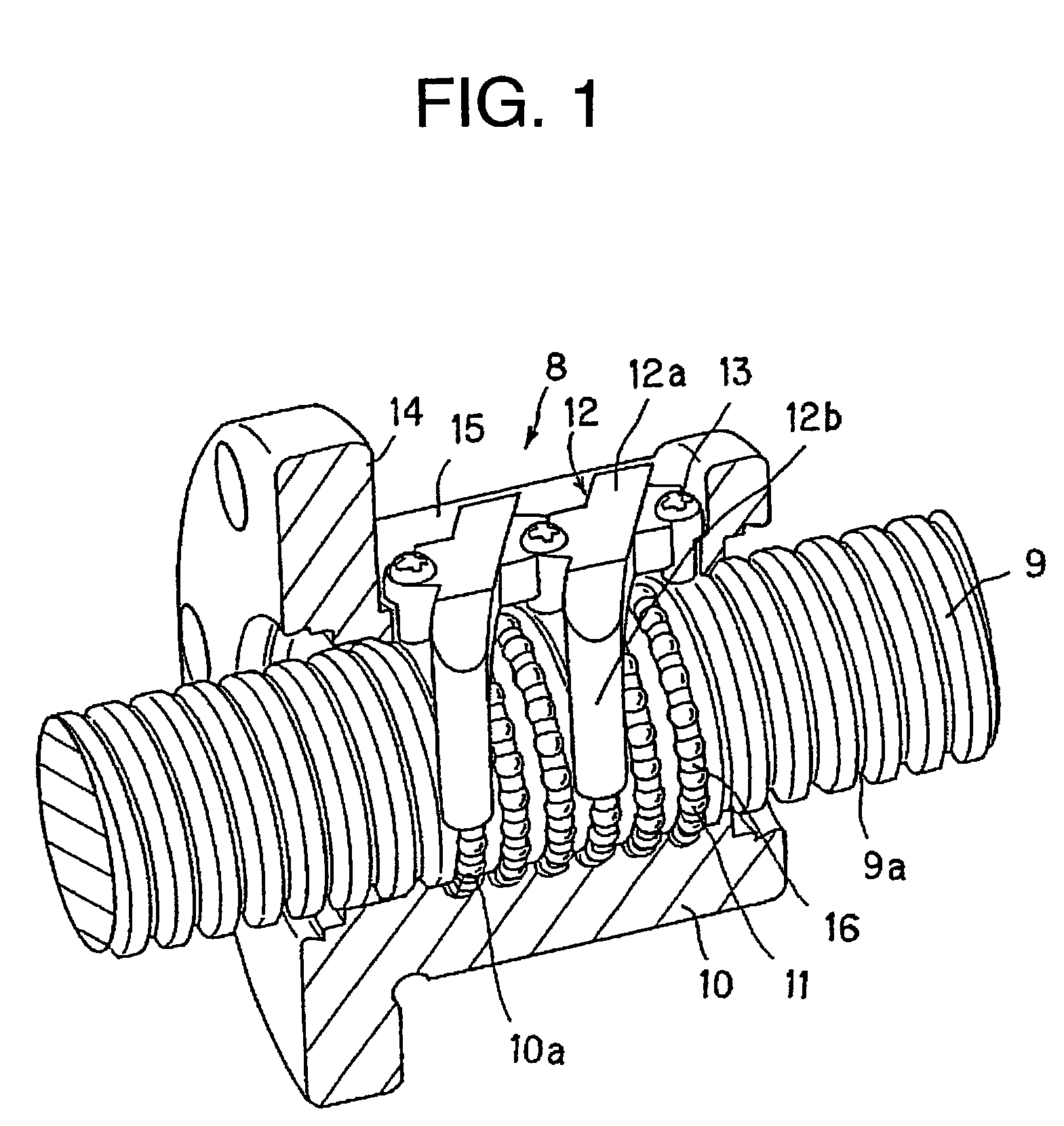
[0066]FIG. 1 shows a ball screw to which a circulation member according to one embodiment of the present invention is mounted. With reference to FIG. 1, a ball screw 8 comprises a screw shaft 9 having a spiral ball rolling groove 9a formed on its outer peripheral surface, a nut member 10 having a spiral loaded rolling groove 10a formed on its inner peripheral surface so as to oppose to the ball rolling groove 9a of the screw shaft 9 and a number of balls 11, 11, - - - , 11 rolling in a passage, as loaded rolling passage, formed by the ball rolling groove 9a and the loaded rolling groove 10a.

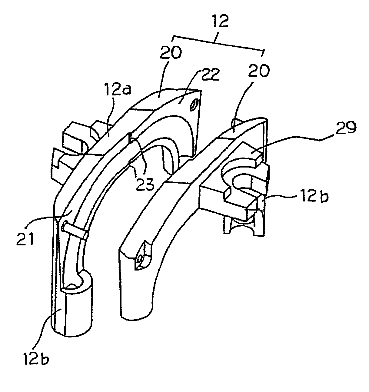
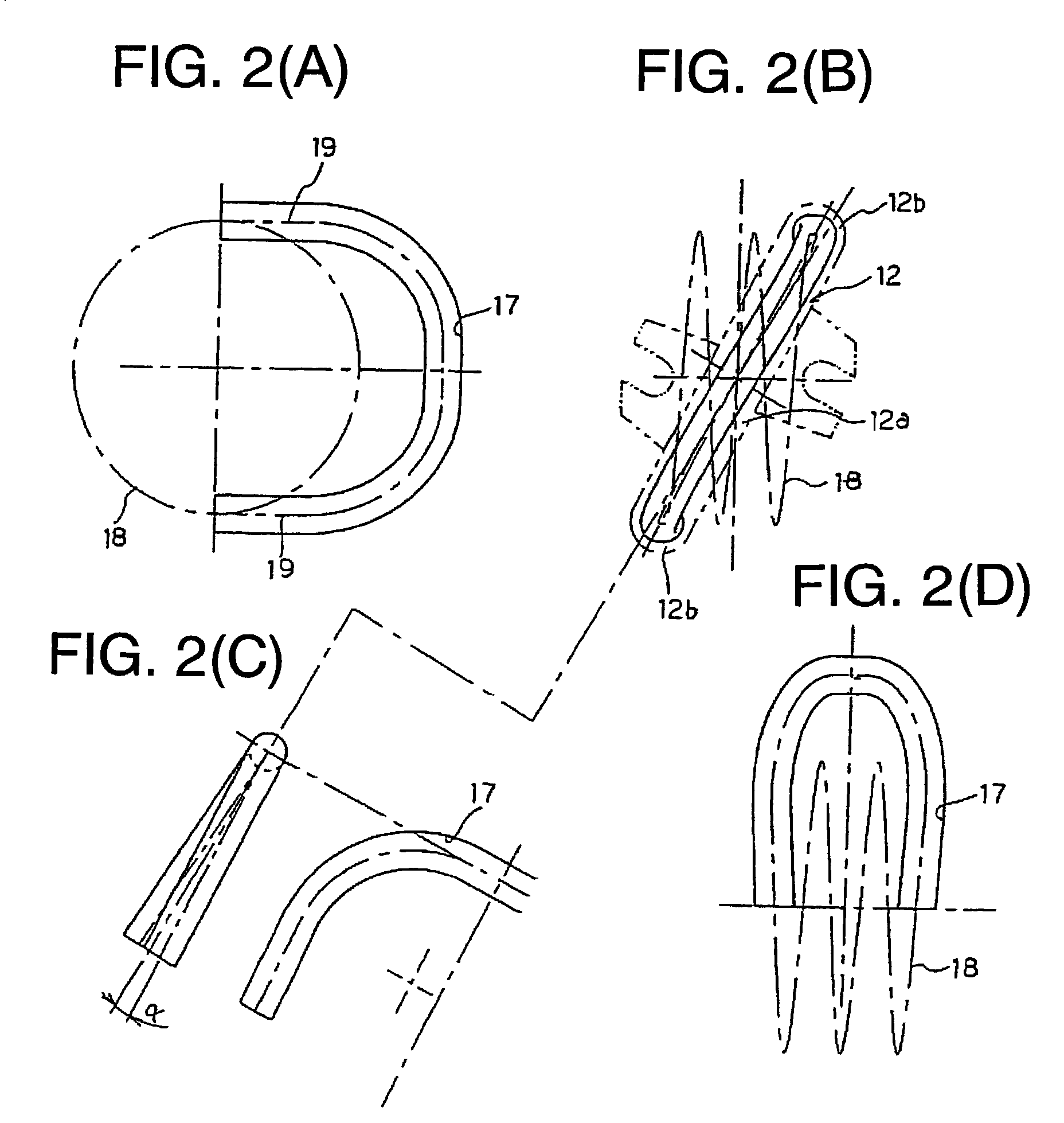
[0067]The nut member 10 is equipped with two, for example, return pipes 12 as circulation members or parts. The return pipe 12 constitutes a non-loaded return passage by connecting one and the other ends of the loaded rolling passage. The return pipe 12 provides approximately a portal shape having a central portion 12a and a pair of leg portions 12b, 12b formed at both ends of the central portio...


PUM


Abstract

A circulation member of a ball screw for circulating a ball rolling on a spiral ball rolling groove formed on a screw shaft. The circulation member includes a central portion and a pair of leg portions disposed at both ends of the central portion so as to extend therefrom, the leg portions having inner peripheries having center lines inclined in directions different from each other with respect to a center line of an inner periphery of said central portion. The leg portions also have outer peripheries having center lines being parallel to each other and have thicknesses, different in circumferential directions thereof, at cross sections in directions normal to center lines of the outer peripheries of the respective leg portions.

Description

BACKGROUND OF THE INVENTION[0001]1. Technical Field[0002]The present invention relates to a circulation member or part for circulating balls of a ball screw and also relates to a ball screw using the circulation member.[0003]2. Related Art[0004]A ball screw generally comprises a screw shaft having an outer peripheral surface on which a ball rolling groove having a spiral or helical shape is formed, a nut member having an inner peripheral surface on which a ball rolling groove having a spiral or helical shape is formed, and a number of balls disposed between a loaded ball rolling passage formed by the ball rolling grooves of the screw shaft and nut member. In this structure, when the screw shaft is rotated relatively to the nut member, the balls roll in the loaded rolling passage formed by the screw shaft and the nut member.[0005]FIG. 9 shows one example of a nut member, to which a return pipe 3 as a circulation member is mounted so as to connect one and the other end portions of a l...

Claims


Application Information

Patent Timeline
IPC IPC(8): F16H25/24F16C33/37F16H25/22
CPCF16C33/3706F16H25/2214Y10T74/19749Y10T74/19767F16H25/22
Inventor MICHIOKA, HIDEKAZUABE, YASUYUKINIWA, HIROSHIIIDA, KATSUYAKADONO, TOSHIAKISHIRAI, TAKEKISHOJI, HIRONORI
Owner THK CO LTD
Why Eureka
Try Eureka