Oil pan structure

a technology of oil pan and structure, which is applied in the direction of lubrication of auxiliaries, lubrication of lubricating elements, pressure lubrication, etc., can solve the problems of deterioration of casting properties of cylinder blocks, increased weight, and complicated configuration, so as to achieve the effect of improving the manufacturing efficiency of the oil pan and ensuring the flow of oil

Active Publication Date: 2006-05-09
AICHI MASCH IND CO LTD +1
View PDF7 Cites 6 Cited by
  • Summary
  • Abstract
  • Description
  • Claims
  • Application Information

AI Technical Summary

Benefits of technology

[0007]The present invention is made by taking the problems in the conventional technique mentioned above into consideration, and it is an object of the present invention to make a cylinder block compact, and to reduce weight of the cylinder block and the like.
[0014]In accordance with the present invention, since the oil pump housing is integrally formed with the oil pan by casting, it is not necessary to mount the oil pump to the cylinder block as in the conventional structure, and it is not necessary that the oil pump attachment portion is provided in the cylinder block. Accordingly, it is possible to make the cylinder block compact, to reduce the weight of the cylinder block, and to increase the rigidity of the cylinder block.
[0015]Further, since it is not necessary to mount the oil pump independently, a freedom of layout for mounting an auxiliary machine, such as an alternator or the like can be improved.
[0016]Further, with the arrangement in which the oil pump driving means is disposed at the higher level than the oil surface reserved within the oil pan or is submersed within the oil, it is possible to prevent the oil from bubbling due to an oil agitation by the oil pump driving means, and this leads to reliably prevent an air from being mixed into the oil to lower the discharging performance of the oil pump.
[0019]Further, with the arrangement in which the upper surface of the rib further includes a visor-like portion inclined upward to extend toward the arrangement chamber, it is possible to receive the oil lubricating the timing chain and dropping down to the lower portion of the arrangement chamber by the visor-like portion, to reliably flow the oil into the inner side of the oil pan, and to prevent the oil from entering the side of the oil pump driving means.
[0020]Further, with the arrangement in which the oil pan is divided into an upper oil pan and a lower oil pan, and the oil pump housing is integrally formed with the upper oil pan, the oil pump housing can be integrally formed as a cast product of an aluminum alloy together with the upper oil pan, and the lower oil pan can be produced as a press-molded product. Therefore, the manufacturing efficiency of the oil pan can be improved.

Problems solved by technology

However, in the conventional structure, since the oil pump is mounted as an independent structure to the cylinder block, there has been a problem that the weight increases.
Further, because an oil pump attachment portion is necessary to be provided in a cylinder block, there has been problems, such as problems that the configuration is complicated, and a casting property of the cylinder block is deteriorated.

Method used


Image

  • Oil pan structure
  • Oil pan structure
  • Oil pan structure

Examples


Embodiment Construction

[0028]A description will be given below with regard to an embodiment of the present invention with reference to the accompanying drawings.

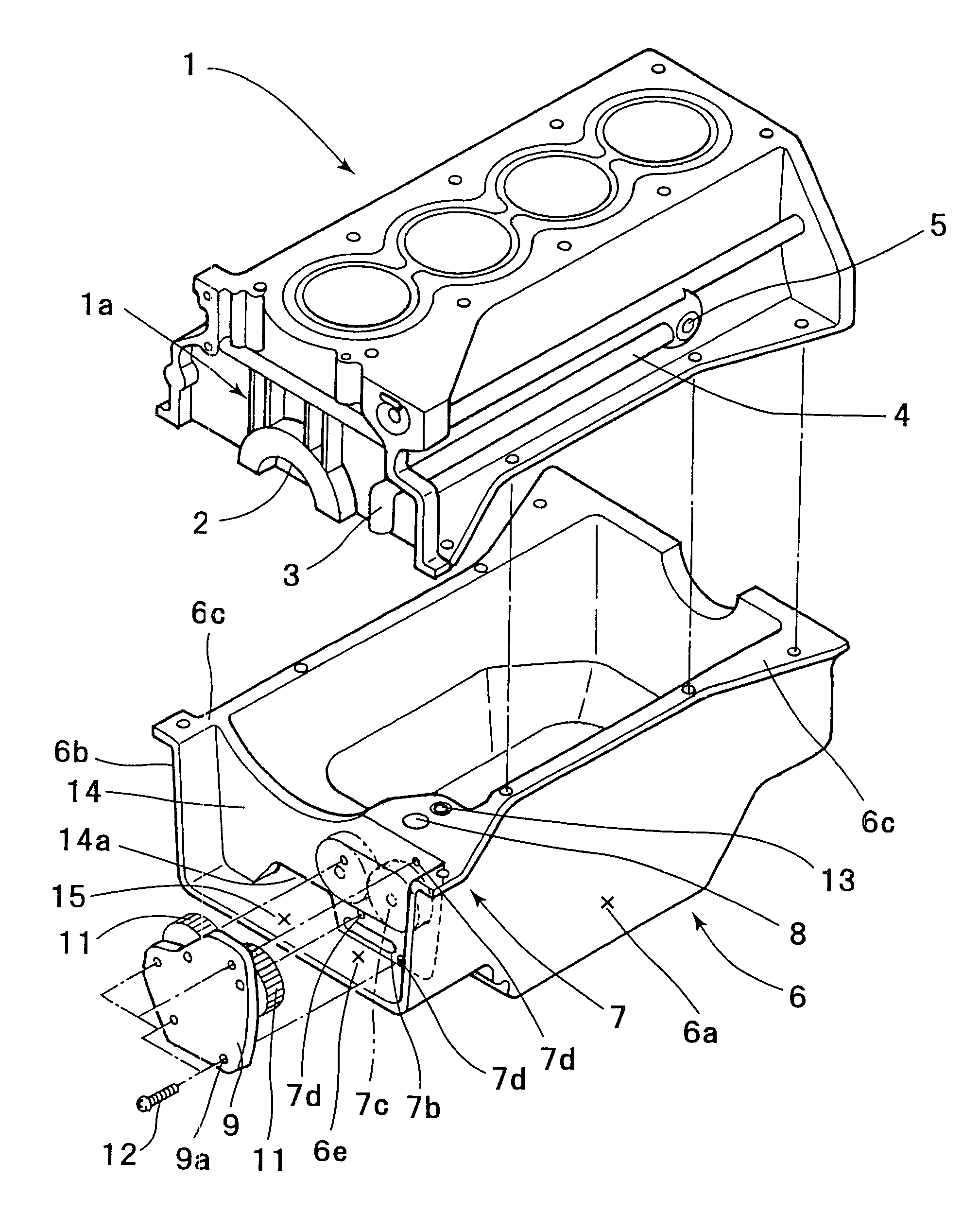
[0029]FIG. 1 is an exploded perspective schematic view of a cylinder block, an oil pan and a mounting member thereof.

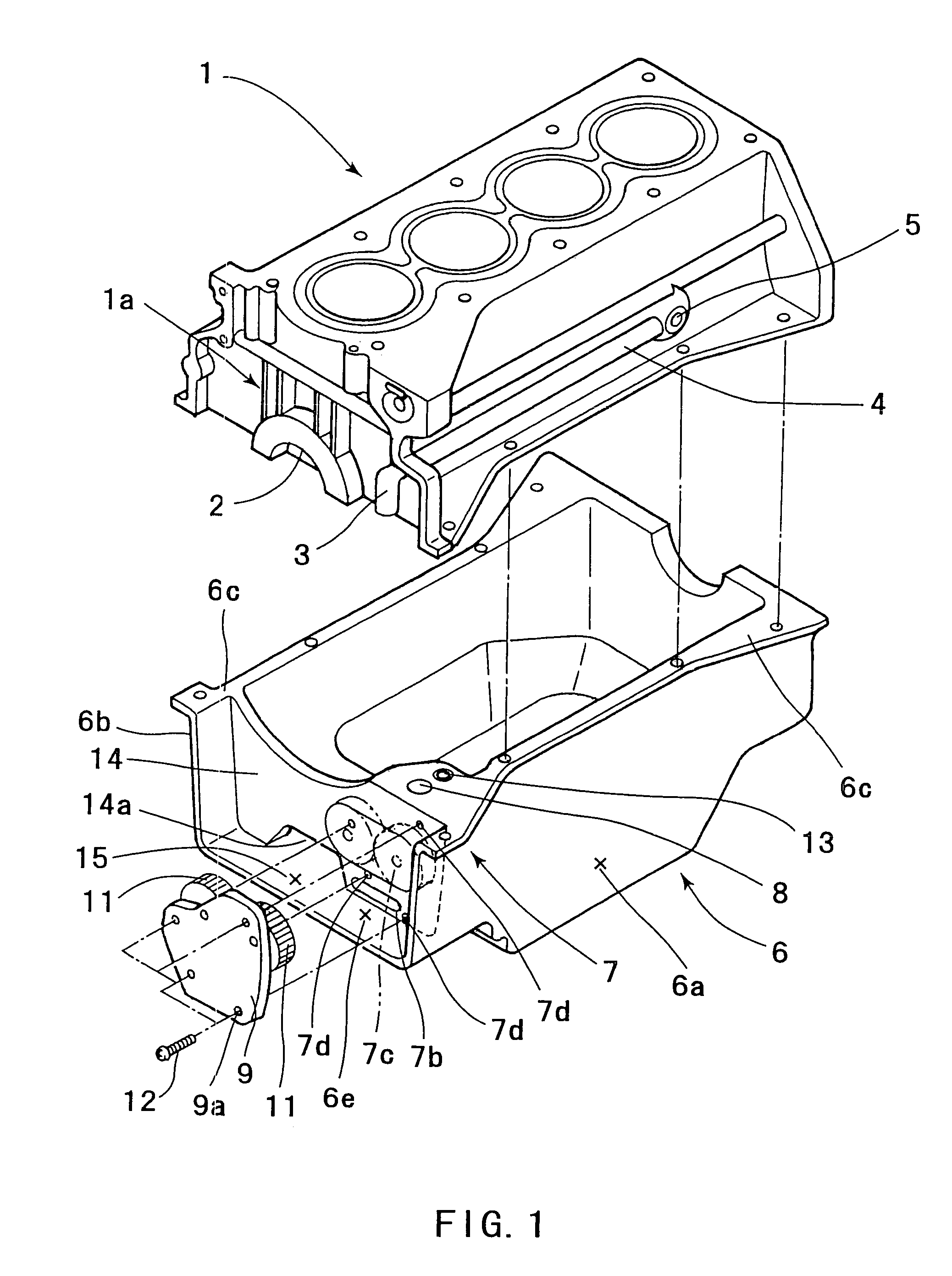
[0030]Further, FIG. 2 is a plan schematic view of the oil pan.

[0031]Further, FIG. 3 is a partly vertical cross sectional schematic view of the oil pan.

[0032]Further, FIG. 4 is a front elevational schematic view of the oil pan as seen from an arrangement chamber side.

[0033]In these figures, a crank shaft bearing portion 2 is formed in a central portion of a lower surface of a cylinder block 1; a vertical oil passage 3 is formed to extend along a right side surface in an upward direction from the lower surface in an upright manner; a horizontal oil passage 4 is formed so as to extend in a horizontal direction from an upper end of the vertical oil passage 3; and it is constructed such that an oil is supplied to each of the portions of ...


PUM


Abstract

An oil pan (6) is mounted to a lower surface of a cylinder block (1) in order to reserve an oil. An oil pump housing (7) is cast integrally with the inner side of the right side surface (6a) of the oil pan (6). A rib (14) is formed in order to connect the right side surface (6a) and a left side surface (6b) of the oil pan (6).

Description

BACKGROUND OF THE INVENTION[0001]1. Field of the Invention[0002]The present invention relates to a structure of an oil pan of an internal combustion engine.[0003]2. Description of the Related Art[0004]Conventionally, as a technique for improving a mounting rigidity and a mounting stability of an oil pump to an engine, for example, there has been proposed a technique disclosed in Japanese Unexamined Patent Publication No. 2002-339712.[0005]In the conventional technique, an oil pump is mounted to a bearing cap provided in a lower surface of a cylinder block by a bolt, as well as to the cylinder block, whereby a mounting rigidity and a mounting stability are improved. However, in the conventional structure, since the oil pump is mounted as an independent structure to the cylinder block, there has been a problem that the weight increases.[0006]Further, because an oil pump attachment portion is necessary to be provided in a cylinder block, there has been problems, such as problems that t...

Claims


Application Information

Patent Timeline
Patent Type & Authority Patents(United States)
IPC IPC(8): F01M1/02F01M11/00F02F7/00
CPCF01M11/0004F01M2011/0079
Inventor OHTA, YASUKIHADA, MASATOSHIKUROKAWA, HIROYUKI
Owner AICHI MASCH IND CO LTD
Why Eureka
Try Eureka