
Dispenser with material-recognition apparatus and material-recognition method

a technology of material recognition and dispenser, applied in the field of dispensers, can solve the problems of lack of capability, affecting the operation of the dispenser, and the selection of the optimal sheet material can be unduly complicated, so as to minimize the risk of dispenser failure

Inactive Publication Date: 2006-05-09
ALWIN MFG
View PDF30 Cites 157 Cited by
  • Summary
  • Abstract
  • Description
  • Claims
  • Application Information

AI Technical Summary

Benefits of technology

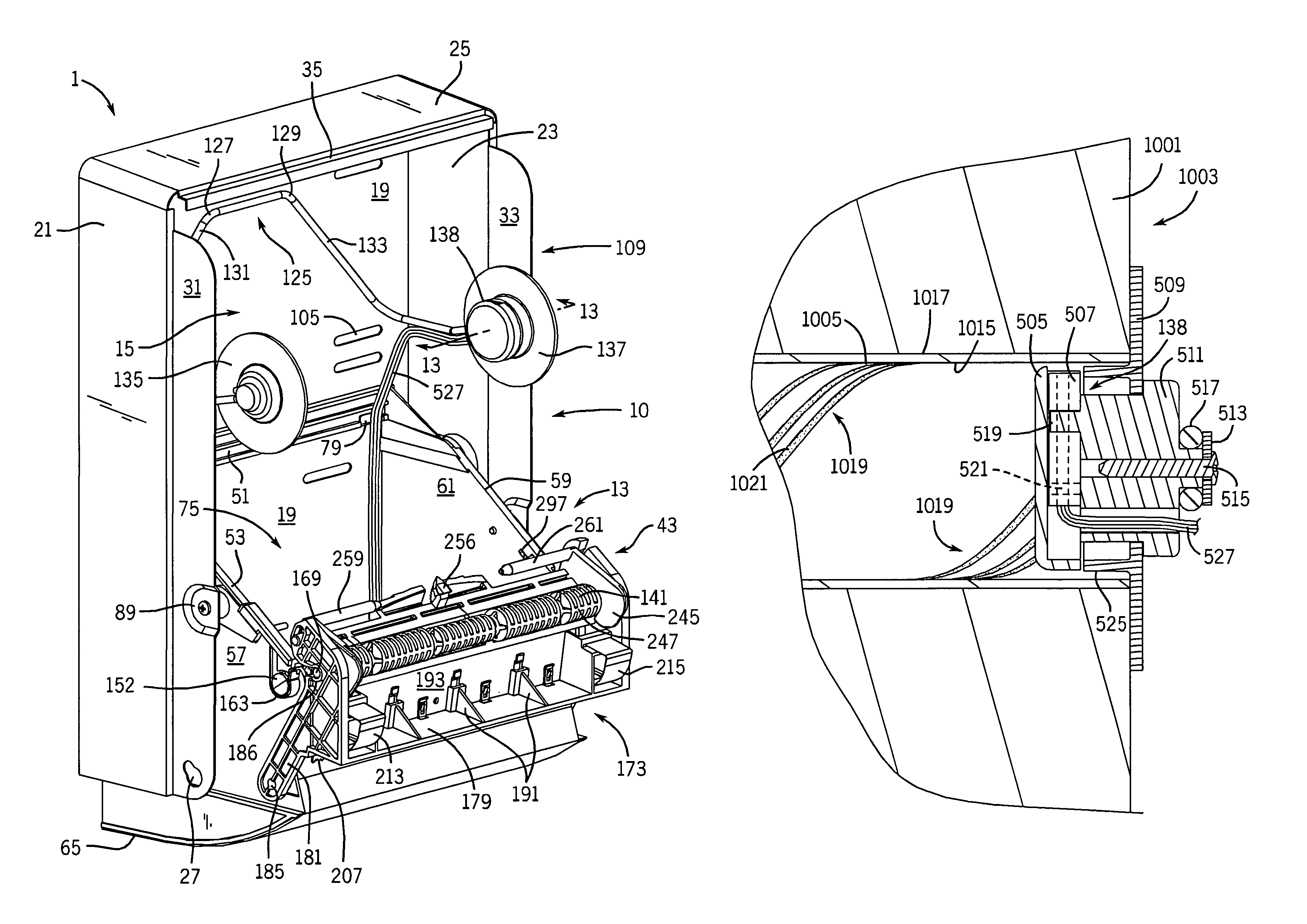
[0011]The invention is directed to improved dispenser apparatus for dispensing flexible sheet material in the form of a web. The dispenser of the invention includes apparatus for recognition of the sheet material to be dispensed and the invention includes a method of material recognition. The dispenser and material-recognition apparatus may be adapted for use with sheet material of any suitable form including paper towel, toilet tissue, kraft paper, cotton-based cloth, plastic sheet, films and the like. Advantageously, such material-recognition apparatus is not limited for use with any particular dispenser apparatus and may be adapted to operate with the structure of the particular dispenser of interest. The recognition apparatus enables dispenser operation with sheet material sourced for the dispenser thereby providing the dispenser owner with a degree of control over the sheet material used with the dispenser. Advantageously, this permits the dispenser to be used with sheet material tailored for optimal dispenser operation while minimizing the risk of dispenser failure caused by premature or unwanted tearing, buckling or folding of the sheet material.

Problems solved by technology

An important issue affecting these types of dispensers involves the need to ensure that the dispenser operates reliably and without the need for constant service by an attendant.
Further, the dispenser must withstand the rigors of operation under difficult environmental conditions such as the high-humidity environments typical of athletic locker rooms and public washrooms.
However, selection of the optimal sheet material can be unduly complicated because there are many commercial sources of sheet material and because seemingly identical types of sheet material may, in fact, not have the properties required for optimal dispenser operation.
Dispensers presently available lack any capability to identify sources of sheet material which are designed for use with such dispensers, potentially enabling dispenser operation with sheet material not suited for use with the dispenser and contributing to unreliable operation of the dispenser.

Method used


Image

  • Dispenser with material-recognition apparatus and material-recognition method
  • Dispenser with material-recognition apparatus and material-recognition method
  • Dispenser with material-recognition apparatus and material-recognition method

Examples


embodiment 1

[0128]In the motor-driven embodiment 1, the control circuit 49 affects the electric motor 267 such that, in the dispenser-enabled state, motor operation is triggered responsive to a signal from the input device 537 and, in the dispenser-disabled state, the electric motor 267 is disabled. In the manually-driven dispenser 3, control circuit 49 generates an “interlock signal” based on the code comparison and presents such interlock signal to the interlock device 50. The interlock signal is any signal which is capable of enabling or disabling the dispenser interlock device 50. The interlock device 50 receives the interlock signal and sets a dispenser-enabled state in which the dispenser 3 is enabled for operation if there is agreement in the above code comparison. Alternatively, interlock device 50 sets a dispenser-disabled state in which the dispenser is disabled if no such agreement is found.

[0129]The microcontroller 403 and related control circuit 49 components 333 for dispenser embo...

embodiment 3

[0145]An optional material transfer event will be described in connection with FIGS. 29–30 which represent a motor-driven dispenser 1 with an optically-based “CoreCheck” routine as described below in connection with steps 651–672. Such description is applicable to the manually-driven dispenser embodiment 3 because the structure and operation of the transfer mechanism 227 for dispenser 3 is identical to that for motor-driven dispenser 1 with the optically-based CoreCheck. FIGS. 22–30 represent the state of dispenser 1 in which a previously recognized sheet material stub roll 39 is mounted on support 107 while a full sheet material roll 41, following material recognition, is mounted on support 109.

[0146]Referring first to FIG. 34A, that figure represents the material-recognition steps common to the material-recognition apparatus 10 of all dispenser embodiments 1, 3. The material-recognition steps of the present invention are described in connection with recognition of a sheet material...


PUM


Abstract

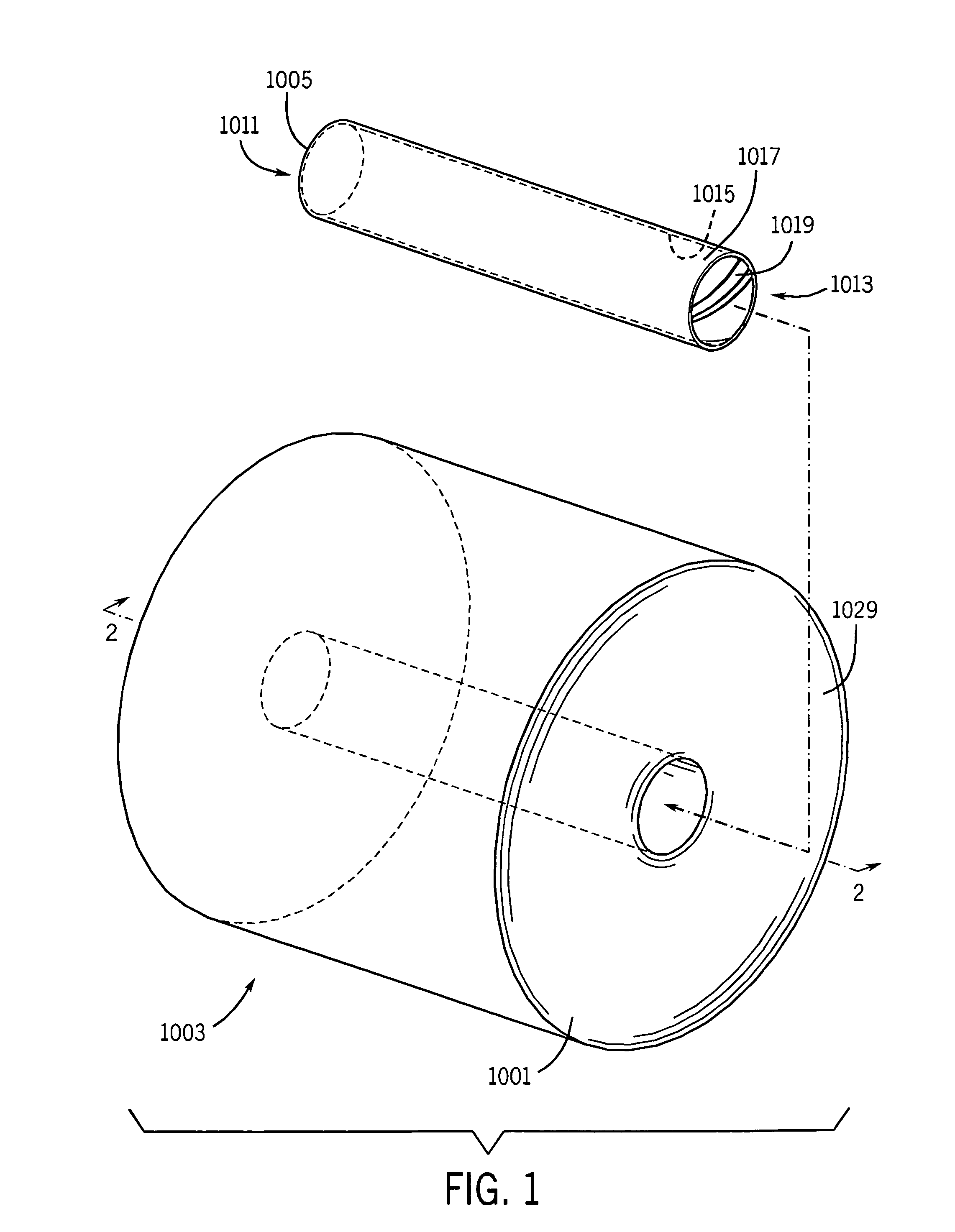
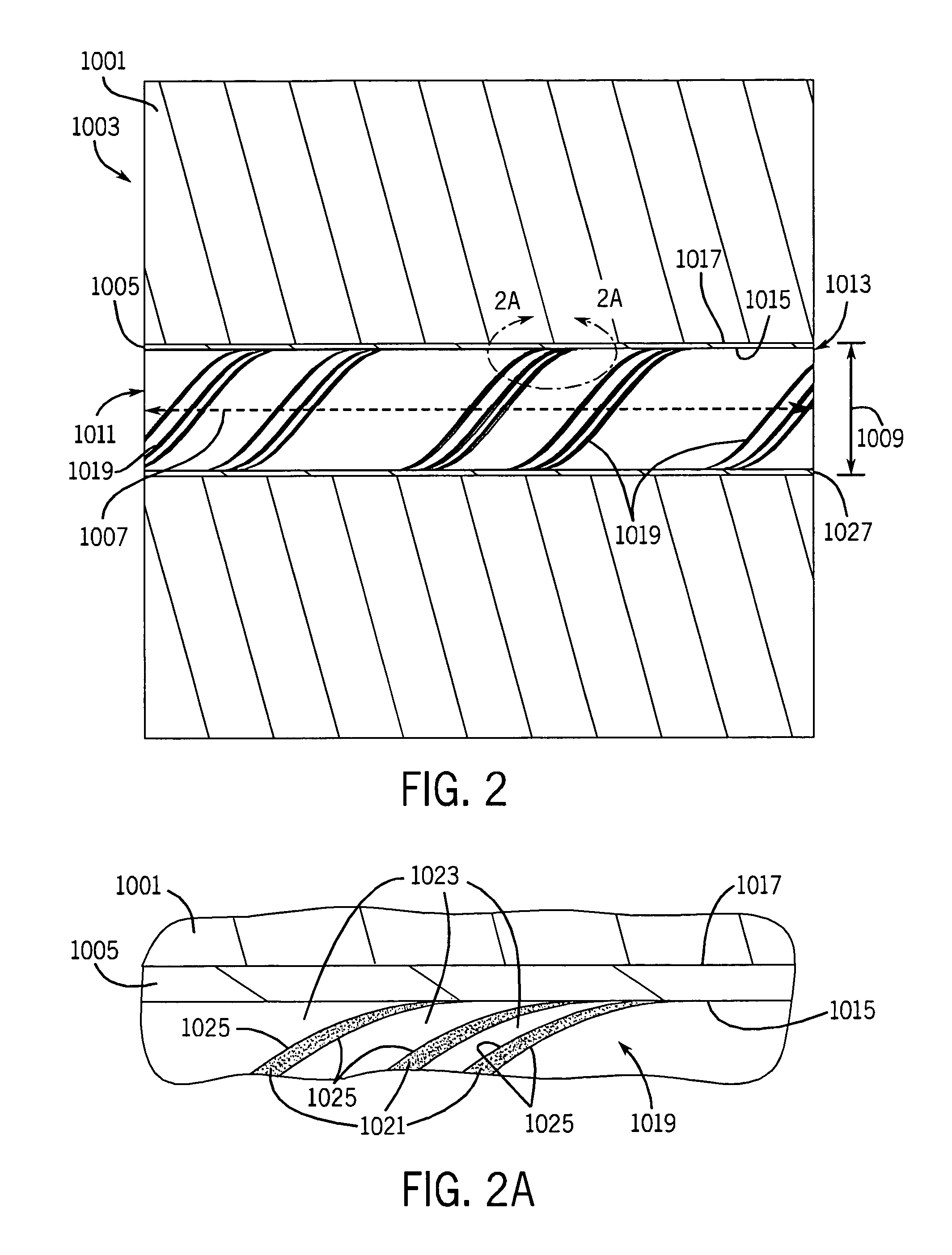
Dispenser apparatus for dispensing flexible sheet material including material-recognition apparatus permitting the dispenser to recognize sheet material from an authorized source and to be enabled for operation with such material. The dispenser preferably includes standard mechanical components for dispensing sheet material from the dispenser including a housing, structure for supporting a roll of sheet material, drive and tension rollers forming a nip through which the sheet material is displaced as the drive roller rotates and drive apparatus in power-transmission relationship with the drive roller. The material-recognition apparatus includes a sensor mounted in the dispenser housing and in position to scan a code, preferably located on the core on which the sheet material is wound. The sensor generates a code signal corresponding to the code. A control circuit operatively connected to the sensor is adapted to receive the code signal and compare the code represented by said code signal to at least one code in a code database. The dispenser is placed in a dispenser-enabled state capable of dispensing sheet material corresponding to agreement between the codes and a dispenser-disabled state in which the dispenser is disabled when no such code agreement exists.

Description

BACKGROUND OF THE INVENTION[0001]1. Field of the Invention[0002]This invention is related generally to dispenser apparatus and, more particularly, to apparatus for dispensing flexible sheet material including apparatus for recognition of the sheet material to be dispensed.[0003]2. Description of Related Art[0004]Dispenser apparatus for dispensing flexible sheet material, such as paper towel and the like, are well known in the art. Such dispensers typically discharge sheet material provided in the form of a sheet material roll. The sheet material roll comprises a sheet material web wound about a core. The core is typically in the form of a cylindrically-shaped hollow core made of cardboard, plastic or a like material. The core typically has an inner surface and open ends provided to mount the sheet material roll within the dispenser. The sheet material roll may be mounted within the dispenser, for example, by means of a yolk with roll holders or mandrels adapted for insertion into th...

Claims


Application Information

Patent Timeline
IPC IPC(8): B65H43/00
CPCA47K10/3845A47K10/36A47K10/3612A47K10/3625A47K10/3637A47K10/3687A47K2010/3681A47K2010/3693
Inventor RODRIAN, JAMES A.HANSEN, LAWRENCE R.KANANEN, DANIEL C.PAAL, ALAN P.BUCZKIEWICZ, ROBERT T.
Owner ALWIN MFG
Learn More