Pneumatically-controlled hydraulic vibration-damping support

a hydraulic and pneumatic technology, applied in the direction of vibration dampers, machine supports, machine frames, etc., can solve the problems of large axial size of damping supports, large thickness of said plates, and large weight of said damping supports, etc., and achieve the effect of reducing the drawbacks

Active Publication Date: 2006-05-09
HUTCHINSON SA
View PDF21 Cites 10 Cited by
  • Summary
  • Abstract
  • Description
  • Claims
  • Application Information

AI Technical Summary

Benefits of technology

[0011]By means of these provisions, it is not necessary to use a thick plate in order to obtain a second constricted passageway having the desired resonant frequency. This results in a saving in weight and in overall size in the axial direction (i.e. perpendicularly to the above-mentioned plate). In addition, advantageous use is made of the volume of the additional hydraulic chamber by making provision for it to receive the tube that defines the second constricted passageway, thereby further improving the compactness of the support in the axial direction, said tube being surrounded radially by the side wall of the cup, a portion of the second pouch lying between the tube and said side wall.

Problems solved by technology

When it is desired to obtain said second resonant frequency, that results in said plate having large thickness, and hence large weight, and in the vibration-damping support having relatively large axial size.

Method used


Image

  • Pneumatically-controlled hydraulic vibration-damping support
  • Pneumatically-controlled hydraulic vibration-damping support

Examples


Embodiment Construction

[0030]In the various figures, like references designate elements that are identical or similar.

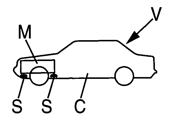
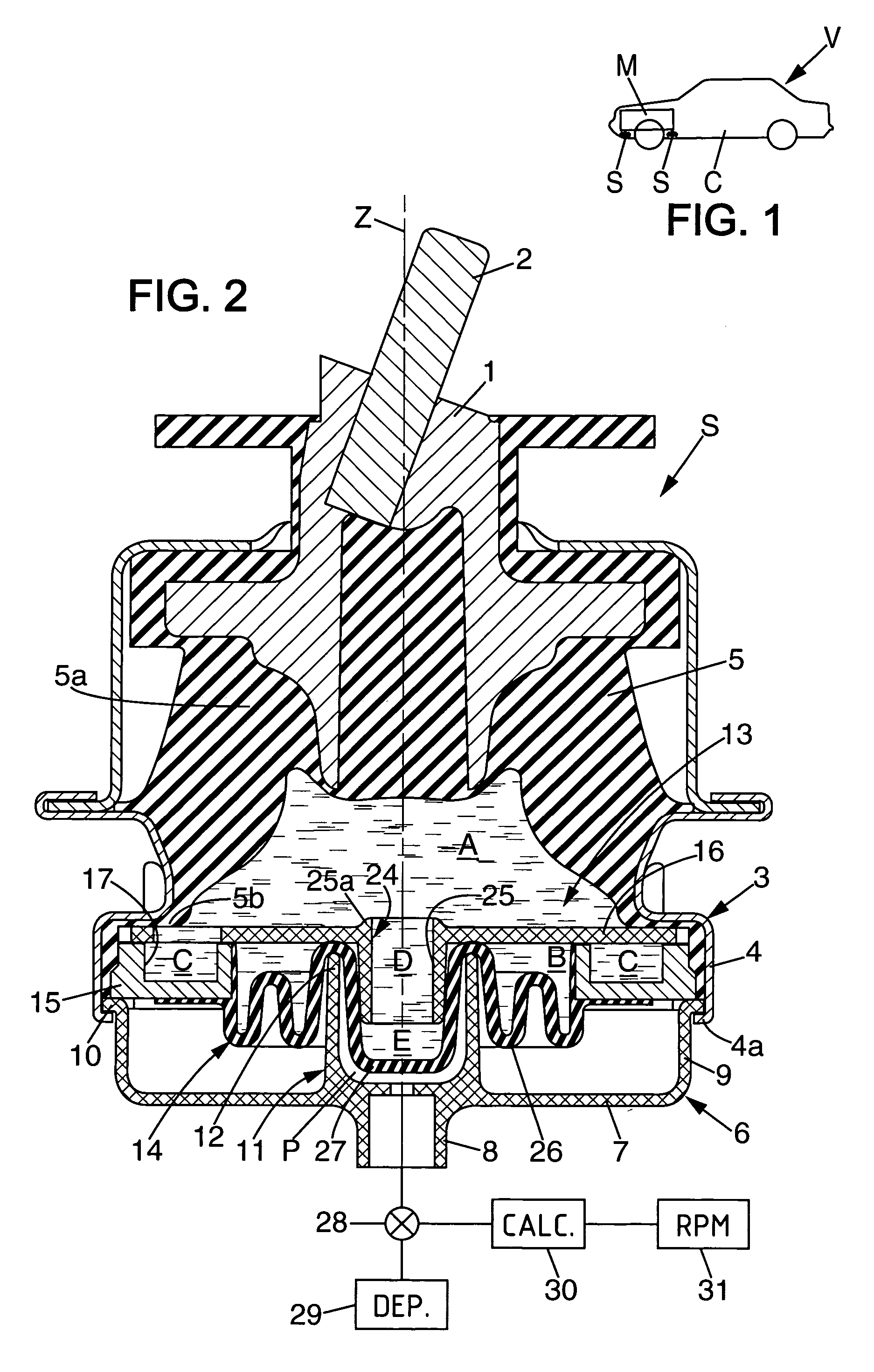
[0031]FIG. 1 shows a motor vehicle V whose body C supports an engine M by means of at least one hydraulic vibration-damping support S such as, for example, the support shown in FIG. 2 for a first embodiment of the invention.

[0032]The vibration-damping support S comprises:[0033]a first rigid strength member 1 in the form of a metal base which is secured to a pin 2 that extends upwards along a vertical central axis Z and that serves to be fastened, for example, to the engine M of the vehicle;[0034]a second rigid strength member 3, e.g. made of metal, that serves to be fastened, for example, to the body C of the vehicle, and that has, in particular, a ring 4; and[0035]an elastomer body 5 capable of withstanding, in particular, the static forces due to the weight of the engine M, it being possible for said elastomer body to be bell-shaped, for example, the bell shape extending between a top 5a...


PUM


Abstract

A hydraulic vibration-damping support comprising two strength members interconnected by an elastomer body that defines a hydraulic working chamber filled with liquid, which chamber communicates via two passageways with two hydraulic chambers surrounding each other and defined by two juxtaposed pouches formed in a common flexible wall. One of the pouches is surrounded by a pneumatic chamber that can be subjected to suction, and one of the constricted passageways is defined by a tube that projects into said pouch.

Description

FIELD OF THE INVENTION[0001]The present invention relates to pneumatically-controlled hydraulic vibration-damping supports.[0002]More particularly, the invention relates to a hydraulic vibration-damping support designed to be interposed for vibration-damping purposes between first and second rigid elements, said vibration-damping support comprising:[0003]first and second strength members serving to be fastened to the two rigid elements;[0004]a rigid partition comprising at least one plate;[0005]an elastomer body which connects the two strength members together and which co-operates with the partition to define a working chamber filled with liquid;[0006]first and second flexible pouches which co-operate with said rigid partition to define respectively a compensation chamber and an additional hydraulic chamber, which chambers are adjacent and liquid-filled, the compensation chamber being connected to the working chamber via a first constricted passageway filled with liquid and that ha...

Claims


Application Information

Patent Timeline
Patent Type & Authority Patents(United States)
IPC IPC(8): F16F13/00F16F13/10F16F13/26
CPCF16F13/268F16F13/106
Inventor GRASSMUCK, VOLKER
Owner HUTCHINSON SA
Why Eureka
Try Eureka