Powered latch assembly

a technology of latch assembly and latch rod, which is applied in the direction of lighting and heating apparatus, heating types, and domestic stoves or ranges. it can solve the problems of oven, oven, and ultimately the user being unaware of the unsafe state of the oven door, and in a dangerous condition, so as to minimize manufacturing costs, simple and durable structure, and reliable operation

a technology of latch assembly and latch rod, which is applied in the direction of lighting and heating apparatus, heating types, and domestic stoves or ranges. it can solve the problems of oven, oven, and ultimately the user being unaware of the unsafe state of the oven door, and in a dangerous condition, so as to minimize manufacturing costs, simple and durable structure, and reliable operation

US7040674B2Active Publication Date: 2006-05-09HTI TECH & IND LLC

Image

  • Powered latch assembly
  • Powered latch assembly
  • Powered latch assembly

Examples


Embodiment Construction

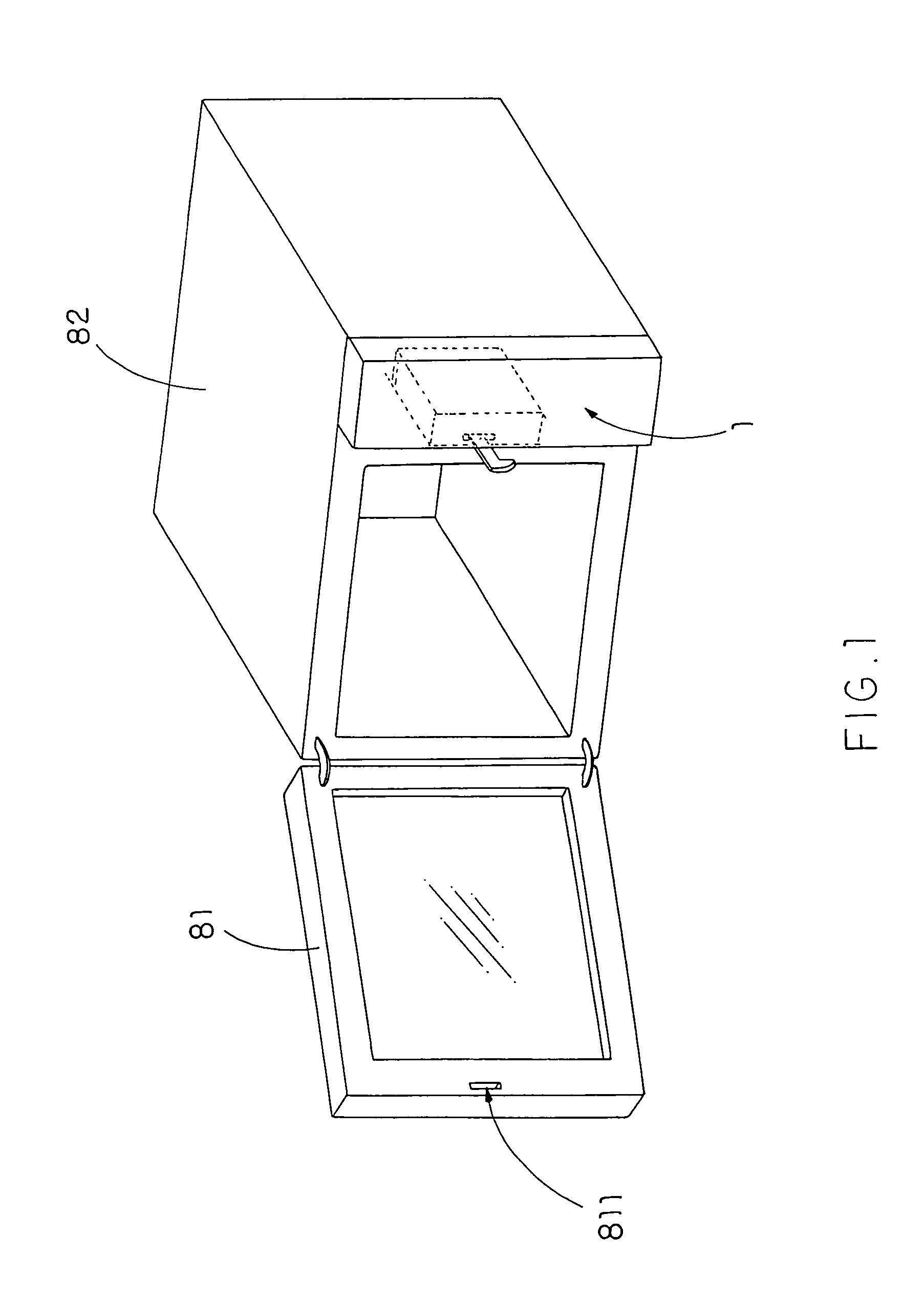
[0032]Referring to FIG. 1 of the drawings, a power lock assembly 1 for locking a door 81, such as an oven door 81 having a lock engaging slot 811 or a engaging socket, pin, etc., to a main housing 82, such as an oven body or an enclosure, is illustrated, in which the power lock assembly 1 comprises a supporting frame 10, a power source, such as a motor assembly 20 or a solenoid, and a locking latch 30.

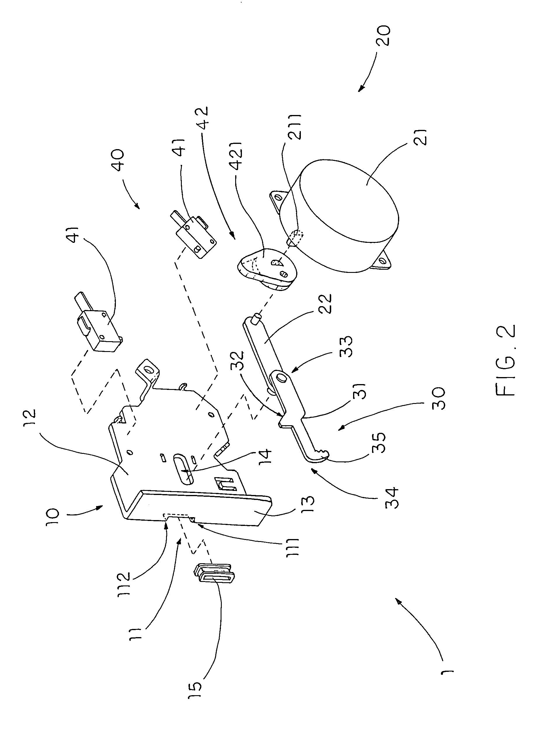
[0033]Referring to FIG. 2 of the drawings, the supporting frame 10 is adapted for mounting on the main housing 82, such as the oven body, and contains a locking slot 11 formed thereon to define first and second slider ends 111, 112 of the locking slot 11. The supporting frame 10 comprises a supporting base 12, and a sidewall 13 outwardly and integrally extended therefrom in which the locking slot 11 is longitudinally formed on the sidewall 12.

[0034]The motor assembly 20 comprises a motor 21, such as an Alternating Current (AC) motor, a Direct Current (DC) motor or a gear motor, support...


PUM


Abstract

A power latch assembly which includes a supporting frame adapted for mounting on a main housing, wherein the supporting frame has a locking slot and defines first and second slider ends thereof; a motor assembly including a power motor supported by the supporting base and adapted for being powered by the main housing, and a driving arm driven by the power motor in a linear movable manner; and a locking latch, defining a first guiding edge and a second guiding edge, having an inner coupling end coupling with the driving arm and an opposed latching end extended outwardly through the locking slot, wherein the driving arm drives the locking latch between a locking position and an unlocked position.

Description

BACKGROUND OF THE PRESENT INVENTION[0001]1. Field of Invention[0002]The present invention relates to a door latch, and more particularly to a powered latch assembly which is capable of converting a rotational driving force delivered by a power source, such as a motor or a solenoid, to a linear movement of a locking latch for locking a door of an enclosure, such as an oven door or sky lights etc.[0003]2. Description of Related Arts[0004]Conventional powered latch assemblies are widely utilized for locking a door, such as an oven door, to a main housing, such as an oven body, for a wide variety of purposes.[0005]For instances, ovens are widely utilized domestically, commercially and industrially. Domestically, small or medium scale ovens are used to cook variety of food. Commercially, medium scale or large scale ovens are utilized to provide catering services. Industrially, large and heavy-duty ovens are utilized for such typically process as heat treatment.[0006]Whatever kind of oven...

Claims


Application Information

Patent Timeline
09 May 2006
Publication
US7040674B2
IPC
E05C3/06; E05B47/00; E05C5/00; F24C15/02
CPC
E05B47/0012; F24C15/022; E05B2047/0024; E05C5/00; E05B2047/0069; Y10T292/1047; Y10T292/1082
Inventors
LOMICKA, JOE; WANG, ZHIRONG