Uveoscleral drainage device

a uveoscleral and drainage device technology, applied in the field of eye implants, can solve the problems of high complication rate, inability to meet the needs of patients, inability to use glaucoma medication, etc., and achieve the effect of facilitating the implantation, and reducing the intraocular pressure in the ey

Active Publication Date: 2006-05-09
YALE UNIV
View PDF26 Cites 170 Cited by
  • Summary
  • Abstract
  • Description
  • Claims
  • Application Information

AI Technical Summary

Benefits of technology

[0019]The shunt may be readily implanted within the eye of a patient in order to reduce the intraocular pressure within the eye. In one example, a first incision in and through the conjunctiva and the sclera at a position posterior to the limbus is made. The shunt is then grasped by the surgeon with, for example, a surgical tool, whereupon the insertion head of the shunt is passed through the first incision and into the supraciliary space of the eye. Next, at least a portion of the shearing edge of the insertion head is inserted into and through the anterior chamber angle into the anterior chamber of the eye. When the insertion head is inserted within the anteri

Problems solved by technology

However, glaucoma medication are not available or practical in many parts of the world, and are inadequate in many patients, despite availability.
While these operations are effective in lowering the intraocular pressure, and are beneficial in desperate cases, they have a high complication rate, including inflammation and further reduction in visual acuity.
Limitations of filtering surgery include failure due to fibrotic closure of the fistula.
Of even greater concern are the complications associated with excessive outflow, which include an intraocular pressure that is too low (hypotony) and a conjun

Method used


Image

  • Uveoscleral drainage device
  • Uveoscleral drainage device
  • Uveoscleral drainage device

Examples


Embodiment Construction

[0038]The present invention is more particularly described in the following examples that are intended as illustrative only since numerous modifications and variations therein will be apparent to those skilled in the art. Thus, the embodiments of this invention described and illustrated herein are not intended to be exhaustive or to limit the invention to the precise form disclosed. They are chosen to describe or to best explain the principles of the invention and its application and practical use to thereby enable others skilled in the art to best utilize the invention. As used in the specification and in the claims, “a,”“an,” and “the” can mean one or more, depending upon the context in which it is used. The preferred embodiment is now described with reference to the figures, in which like numbers indicate like parts throughout the figures and views.

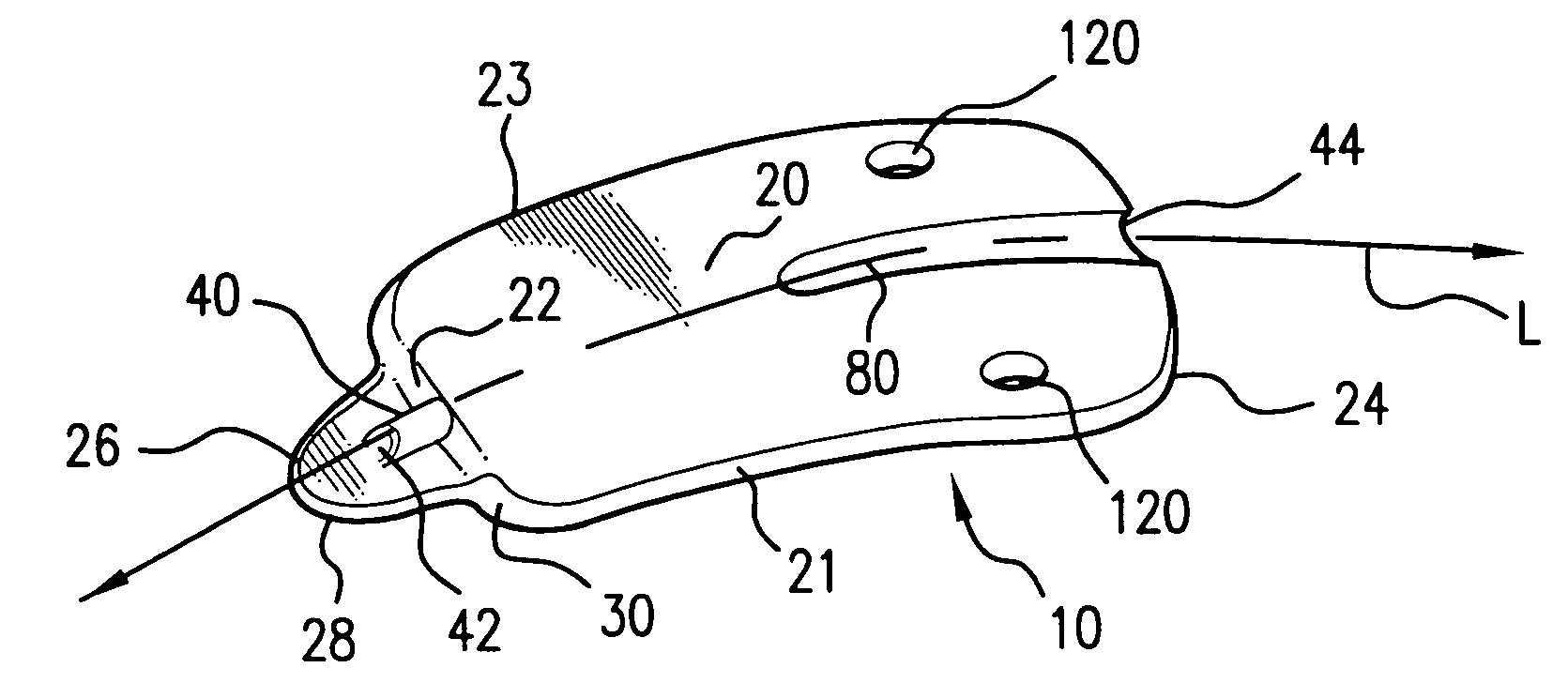
[0039]Referring to FIGS. 3A–5D, examples of uveoscleral drainage devices of the present invention are shown. The implant or shunt 10 ...


PUM


Abstract

An ophthalmic shunt implantable in an eye having an elongate body and a conduit for conducting aqueous humor from an anterior chamber of the eye to the suprachoroidal space of the eye. The elongate body has a forward end and an insertion head that extends from the forward end. The insertion head defines a shearing edge suitable for cutting eye tissue engage thereby. The forward end and the insertion head of the body define a shoulder surface. The conduit has a first end defined on a portion of a top surface of the insertion head. The conduit also extends through the body from the forward end to a back end thereof. The first end of the conduit is spaced from the shearing edge and, in one example, from the shoulder of the body.

Description

[0001]This application claims the benefit of Provisional Application No. 60 / 397,565, filed Jul. 19, 2002.FIELD OF THE INVENTION[0002]The invention relates to eye implants, more particularly, to an ophthalmic shunt and method of using same for use in enhancing uveoscleral drainage in the eye to lower eye pressure.BACKGROUND OF THE INVENTION[0003]Glaucoma, a leading cause of world blindness, is a group of disorders, characterized by irreversible damage to the optic nerve, or glaucomatous optic neuropathy, in which elevated intraocular pressure is the main causative risk factor. The only proven way to prevent the blindness of glaucoma is to control the intraocular pressure.[0004]Clinical management of intraocular pressure can be achieved medically or surgically. Modern medical therapy for glaucoma began in the 1870s, with the introduction of pilocarpine and other cholinergic agonists. In the twentieth century, several compounds were introduced, such as alpha-2 agonists, beta-adrenergic...

Claims


Application Information

Patent Timeline
IPC IPC(8): A61M5/00A61B17/32A61M31/00A61F9/007
CPCA61F9/00781
Inventor SHIELDS, MILTON B.
Owner YALE UNIV
Why Eureka
Try Eureka