Instrument

a technology of instruments and grafts, applied in the field of instruments, can solve the problems of blades may damage the graft, and the problem is particularly obvious, so as to reduce the risk, reduce the number of devices, and pack the bone tigh

Inactive Publication Date: 2006-05-09
INION
View PDF10 Cites 122 Cited by
  • Summary
  • Abstract
  • Description
  • Claims
  • Application Information

AI Technical Summary

Benefits of technology

[0010]An advantage of the invention is that the instrument substantially reduces the risk of damaging a graft inserted into a drilled tunnel.
[0011]The idea underlying an embodiment of the invention is that an expander part insertable into the drilled tunnel is provided between the tip of the first end of the instrument and the blade. The expander part expands the space between a graft and a wall of the drilled tunnel, packing the bone tighter. An instrument provided with a blade to shape the mouth part of a drilled tunnel and an expander part reduces the number of devices necessitated by an operation.
[0012]The idea underlying another embodiment of the invention is that the shaft of the instrument is provided with a cannula to enable a control spike to be inserted therethrough. An advantage of this embodiment is that by inserting such a control spike between a graft and a wall of the drilled tunnel prior to inserting the instrument into the drilled tunnel, the mouth part of the drilled tunnel can be shaped precisely at a correct point since the control spike prevents the instrument from becoming inclined or otherwise disadvantageously positioned. After the mouth part of the drilled tunnel has been shaped, the instrument can be removed from the drilled tunnel while the control spike can be left in its place between the wall of the drilled tunnel and the graft in order to wait for installation of a screw or another fixing element taking place next, utilizing the control spike.
[0013]In an embodiment of the invention, the opening for the control spike in the instrument, i.e. the cannula, also enables a different working order. The operator may first insert the instrument between the drilled tunnel and the graft and, controlled by the cannula in the instrument, position the control spike precisely at the correct place in the drilled tunnel only after the mouth part has been shaped. Surprisingly enough, the cannula in the instrument also enables the number of working phases to be reduced if the instrument and the control spike are inserted simultaneously between the wall of the drilled tunnel and the graft and the control spike has already been inserted into the cannula of the instrument prior to the insertion of the instruments into the drilled tunnel.

Problems solved by technology

The mouth part of the drilled tunnel now being shaped, the blades may damage the graft.
The problem is particularly apparent when a soft tissue graft is used.
The blades may damage the graft even to the extent that it no longer can be used in the operation but has to be replaced by a new one.

Method used


Image

  • Instrument
  • Instrument
  • Instrument

Examples


Embodiment Construction

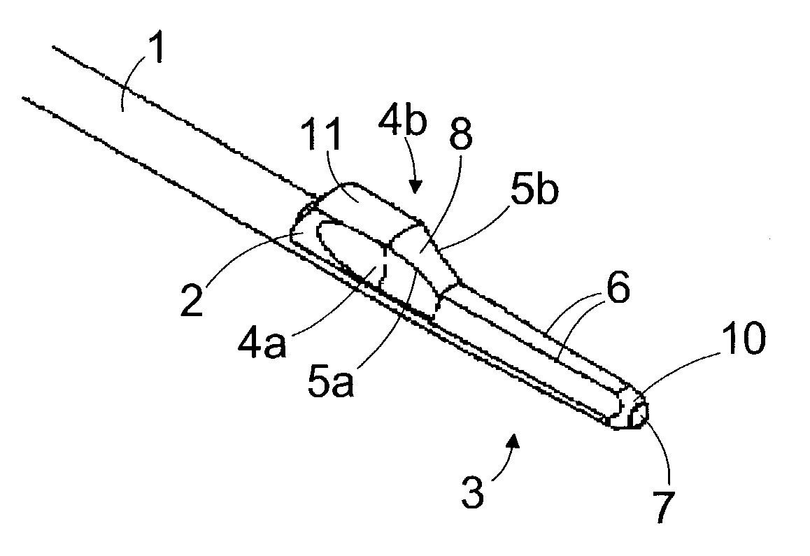
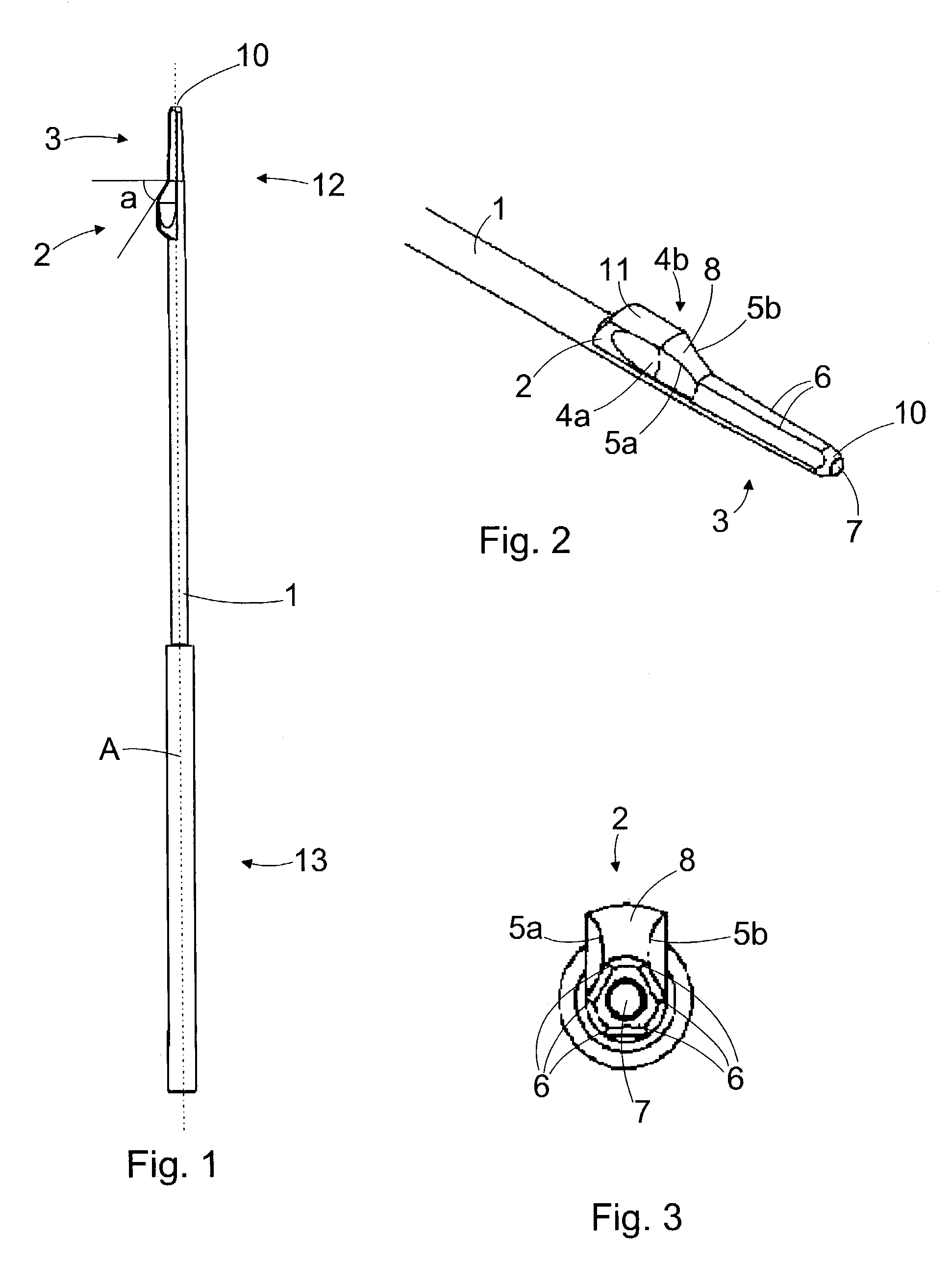
[0021]FIG. 1 is a schematic side view showing an instrument of the invention, FIG. 2 is a schematic view showing a first end of the instrument shown in FIG. 1, and FIG. 3 is a schematic view showing the instrument shown in FIG. 1 as seen from a direction of the first end. The instrument includes a shaft 1 having a first end 12 and a second end 13. The shaft 1 is further provided with a longitudinal axis A. The shaft 1 is manufactured from a sterilizable material, preferably from metal, such as stainless steel. The cross-section of the shaft 1 is circular herein but it may also have another shape. In an operation, the first end 12 of the shaft is inserted into a drilled tunnel. The operator uses the instrument at the second end 13 of the shaft having a handle or a corresponding actuator being arranged therein.

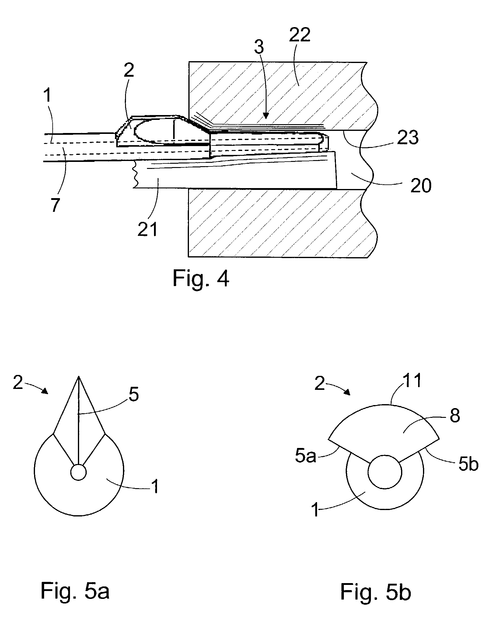
[0022]The first end 12 of the shaft is provided with a projection 2 having a blade 4a, 4b arranged on its both sides, substantially in a direction parallel to the longitudinal a...


PUM


Abstract

An instrument for shaping a mouth part of a drilled tunnel provided in a bone. The instrument includes a shaft having a longitudinal axis and a first and a second end. The first end of the shaft is provided with a projection, which includes a blade for shaping the mouth part of the drilled tunnel when the instrument is turned around the longitudinal axis of the shaft. The instrument is asymmetric at an intersecting surface perpendicular to the longitudinal axis and intersecting with the blade, the instrument thus shaping the surfaces surrounding the first end only substantially within an area corresponding with a turning angle of such a turning movement.

Description

FIELD OF THE INVENTION[0001]The invention relates to an instrument for shaping a mouth part of a drilled tunnel provided in a bone, the instrument including a shaft having a longitudinal axis and a first and a second end, the first end of the shaft being provided with a projection, which includes a blade for shaping the mouth part of the drilled tunnel when the instrument is turned around the longitudinal axis of the shaft.BACKGROUND OF THE INVENTION[0002]Numerous surgical procedures are known wherein connective tissue damaged due to an accident or a disease is repaired and / or replaced. In some of such procedures, tunnels are drilled into a bone, and tissue grafts or artificial grafts are inserted into these tunnels. In the reconstruction of an anterior cruciate ligament (ACL) or a posterior cruciate ligament (PCL), for example, either a soft tissue graft or a bone-tendon-bone graft is fixed to the tunnels drilled into ends of femora and tibiae. In most cases the graft is fixed into...

Claims


Application Information

Patent Timeline
Patent Type & Authority Patents(United States)
IPC IPC(8): A61B17/00A61B17/16
CPCA61B17/1675A61B17/1615
Inventor POHJONEN, TIMOKAIKKONEN, AUVONIEUWENHUIS, JANAHVENJARVI, PIAKARHI, OLLIREUNAMAKI, TIMOKOLJONEN, JUKKA
Owner INION
Why Eureka
Try Eureka