Signal generator with selectable mode control

a signal generator and selectable mode technology, applied in the field of electronic circuits, can solve the problems of affecting the normal operation of surrounding equipment, adding significant bulk and cost to the device, and traditional plls are generally not capable of switching between modes in a smooth manner, and achieve the effect of smooth switching

Inactive Publication Date: 2006-05-09
AVAGO TECH WIRELESS IP SINGAPORE PTE
View PDF19 Cites 67 Cited by
  • Summary
  • Abstract
  • Description
  • Claims
  • Application Information

AI Technical Summary

Benefits of technology

[0009]The present invention meets the above-noted need by providing, in an illustrative embodiment, techniques for smoothly switching between two or more operational modes in a PLL such that the PLL remains substantially locked during any one of the modes and during a transition between any two modes. Operational modes of the PLL provided by the invention may include, but are not limited to, a frequency-slewing mode, a frequency-spreading mode, a fractional-N frequency synthesis mode, and non-slewing mode.
[0010]In accordance with one aspect of the invention, a signal generator circuit includes a controller adapted to generate a divide value in accordance with at least a first control signal, and a divider adapted to divide an output signal of the signal generator circuit by the divisor value. The controller is selectively operable in at least one of a plurality of modes in accordance with at least a second control signal. The controller is configured to calculate each of one or more new divide values so as to vary a frequency of the output signal in accordance with at least one of the first and second control signals. The controller is configured to switch between operational modes and / or switch between divide values, the switching between operational modes and / or divide values being performed in such a manner so as to substantially eliminate discontinuities in the frequency of the output signal.

Problems solved by technology

However, such high frequencies may cause the digital circuitry to radiate signals as electromagnetic energy, and these electromagnetic emissions can interfere with the normal operation of surrounding equipment, a condition often referred to as electromagnetic interference (EMI).
In order to minimize EMI generated by such electronic devices, the electronic devices are often shielded, which adds significant bulk and cost to the devices and is therefore undesirable.
However, traditional PLLs are generally not capable of switching between modes in a smooth manner.
Consequently, the PLL may undesirably generate glitches and / or may become unlocked during the transition between operating modes.

Method used


Image

  • Signal generator with selectable mode control
  • Signal generator with selectable mode control
  • Signal generator with selectable mode control

Examples


Embodiment Construction

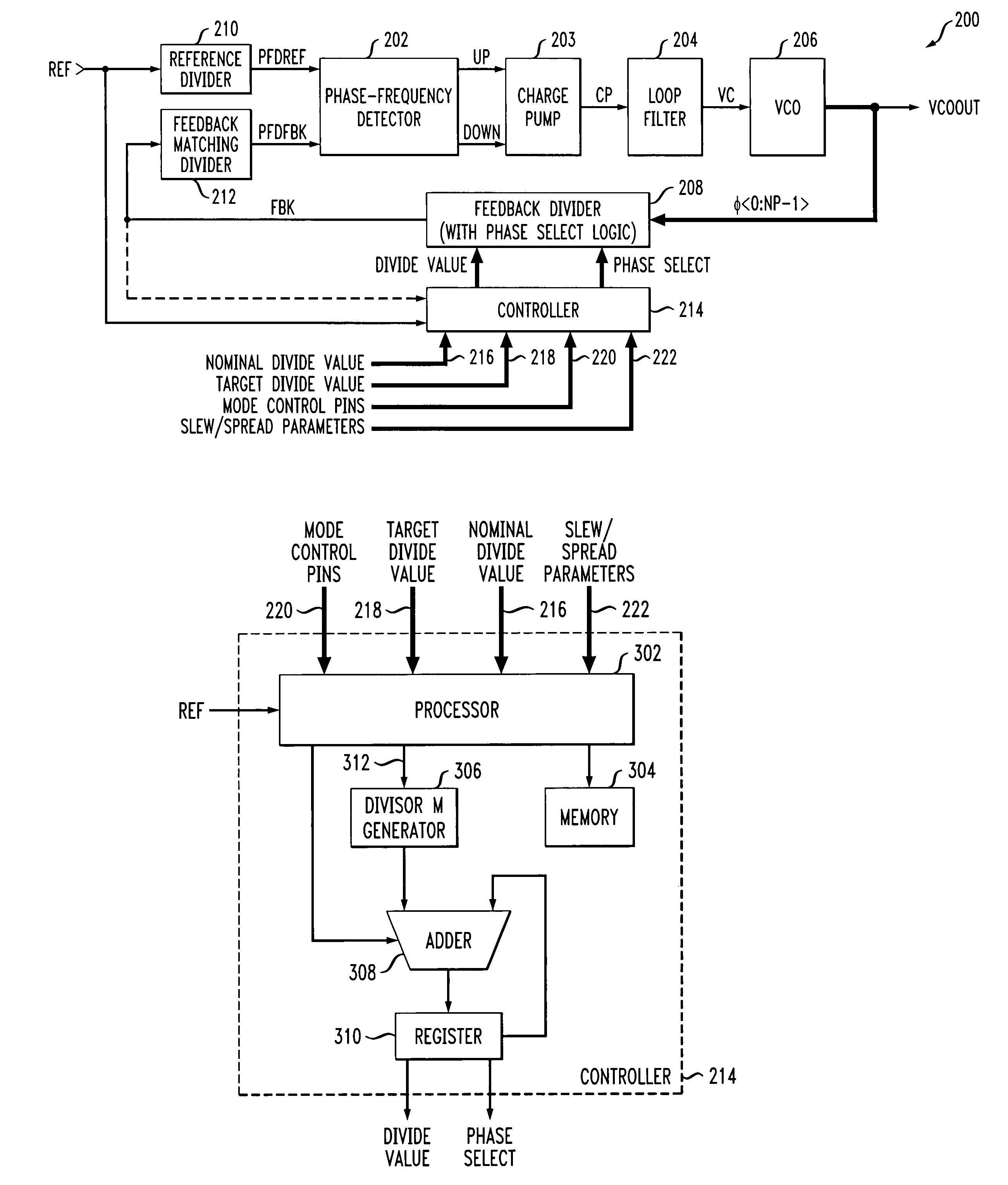
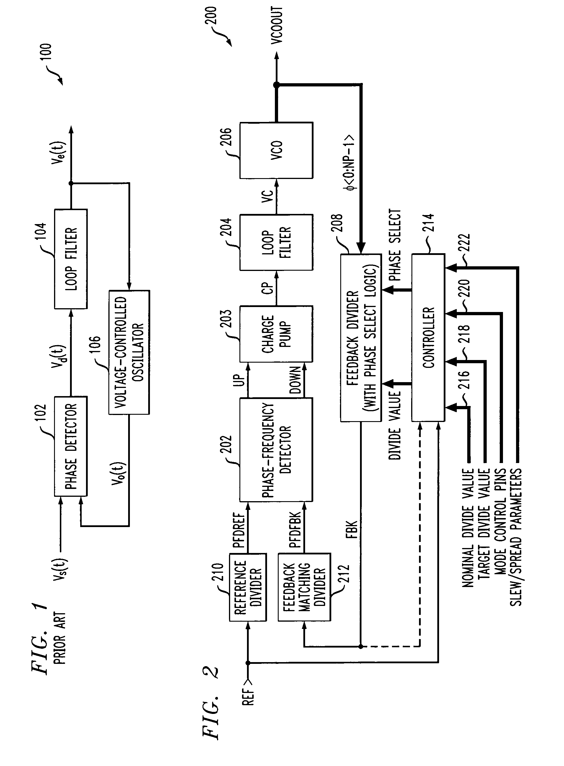
[0019]The present invention will be described herein in the context of an illustrative single-loop PLL circuit and associated integrated circuit implementations thereof. It should be understood, however, that the present invention is not limited to this or any particular PLL architecture. Rather, the invention is more generally applicable to techniques for advantageously controlling a mode of operation of a PLL, or alternative signal generator (e.g., delay-locked loop (DLL)), in a substantially smooth manner, so as to eliminate or substantially reduce glitches or other discontinuities in a frequency of an output signal of the signal generator, thereby substantially maximizing an amount of time that the signal generator remains in a locked state. The signal generator formed in accordance with the present invention is particularly well-suited for use in a wide variety of integrated circuit applications, as well as in non-integrated circuit applications, and in fact may be implemented ...


PUM


Abstract

A signal generator circuit includes a controller adapted to generate a divide value in accordance with at least a first control signal, and a divider adapted to divide an output signal of the signal generator circuit by the divisor value. The controller is selectively operable in at least one of a plurality of modes in accordance with at least a second control signal. The controller is configured to calculate each of one or more new divide values so as to vary a frequency of the output signal in accordance with at least one of the first and second control signals. The controller is configured to switch between operational modes and / or switch between divide values, the switching between operational modes and / or divide values being performed in such a manner so as to substantially eliminate discontinuities in the frequency of the output signal.

Description

CROSS-REFERENCE TO RELATED (APPLICATION(S)[0001]This application relates to commonly assigned U.S. application entitled “Spectrum Profile Control for a PLL and the Like” filed on Aug. 20, 2003 and assigned application Ser. No. 10 / 644,362, the disclosure of which is incorporated by reference herein.FIELD OF THE INVENTION[0002]The present invention relates generally to electronic circuits, and more particularly relates to signal generators.BACKGROUND OF THE INVENTION[0003]In certain electronic devices, it is often necessary to distribute a reference clock signal, or divisions thereof, to various digital circuitry in the devices. The reference clock may operate at high frequencies, such as, for example, above about 350 megahertz (MHz). However, such high frequencies may cause the digital circuitry to radiate signals as electromagnetic energy, and these electromagnetic emissions can interfere with the normal operation of surrounding equipment, a condition often referred to as electromag...

Claims


Application Information

Patent Timeline
Patent Type & Authority Patents(United States)
IPC IPC(8): H03K21/00H03B19/00H03L7/06H03L7/081H03L7/099H03L7/197
CPCH03L7/081H03L7/197H03L7/0996
Inventor BOOTH, RICHARD V.MINEAR, ROGER L.PARIKH, PARAG
Owner AVAGO TECH WIRELESS IP SINGAPORE PTE
Why Eureka
Try Eureka