Electronic endoscope for highlighting blood vessel

a technology of endoscopy and endoscopy, which is applied in the field of image processing of electronic endoscopy, can solve the problems of difficult differentiation between the blood vessel b>3/b> and other tissues such as the mucous membrane b>2/b>, and achieve the effect of increasing the color of the blood vessel and high contras

Inactive Publication Date: 2006-05-09
FUJI PHOTO OPTICAL CO LTD
View PDF124 Cites 57 Cited by
  • Summary
  • Abstract
  • Description
  • Claims
  • Application Information

AI Technical Summary

Benefits of technology

[0014]According to the above-described aspect, in the case where the phase of a blood vessel color is θ1 on a coordinate system in which R-Y is set on the vertical axis and B-Y is set on the horizontal axis, the aspect assumes θ1 to be a reference value and extracts a signal whose phase value of (R-Y)/(B-Y) matches the reference value θ1. On...

Problems solved by technology

On the other hand, since the interior of the living body has pink or reddish coloring, making a disti...

Method used


Image

  • Electronic endoscope for highlighting blood vessel
  • Electronic endoscope for highlighting blood vessel
  • Electronic endoscope for highlighting blood vessel

Examples


first embodiment

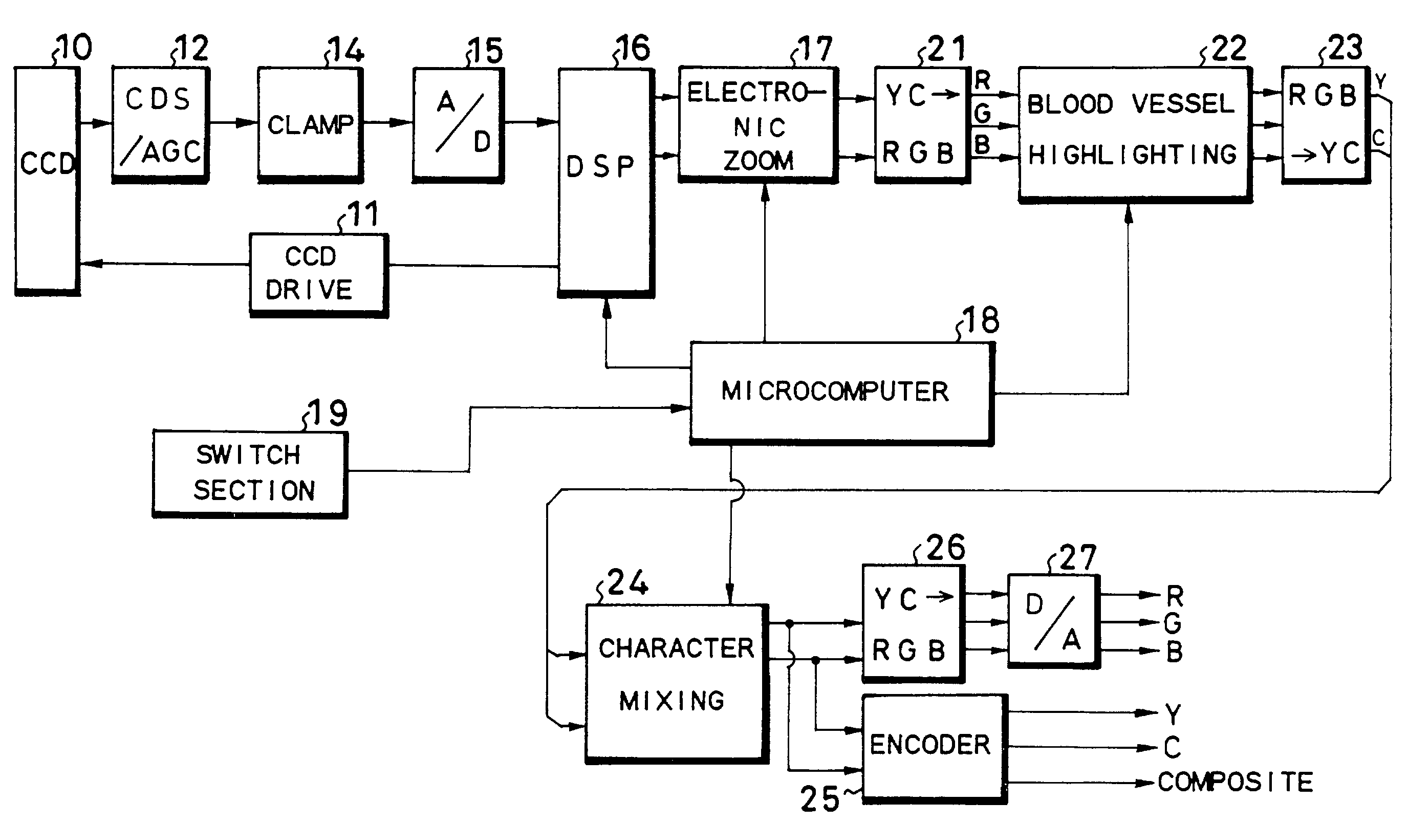
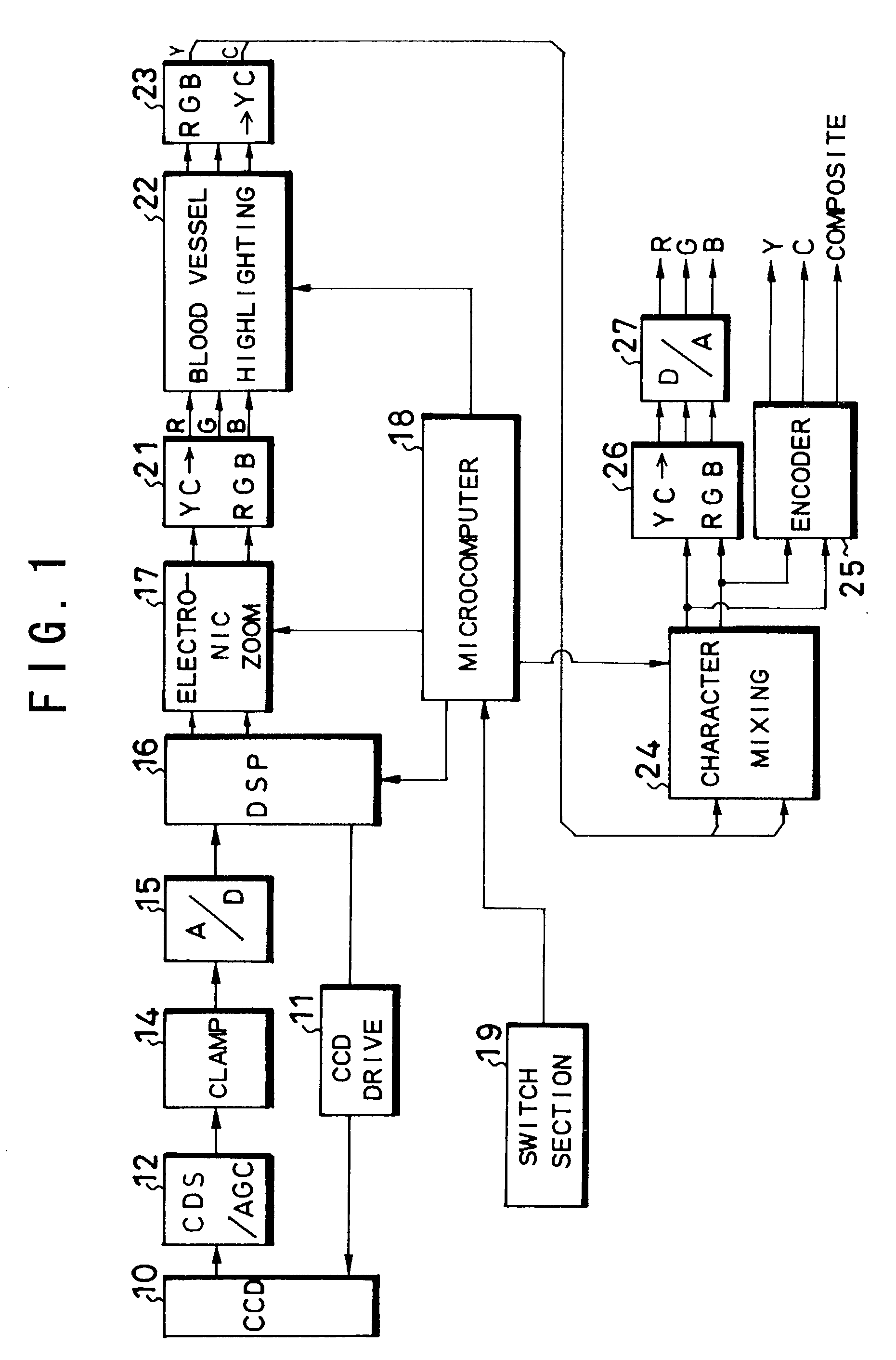
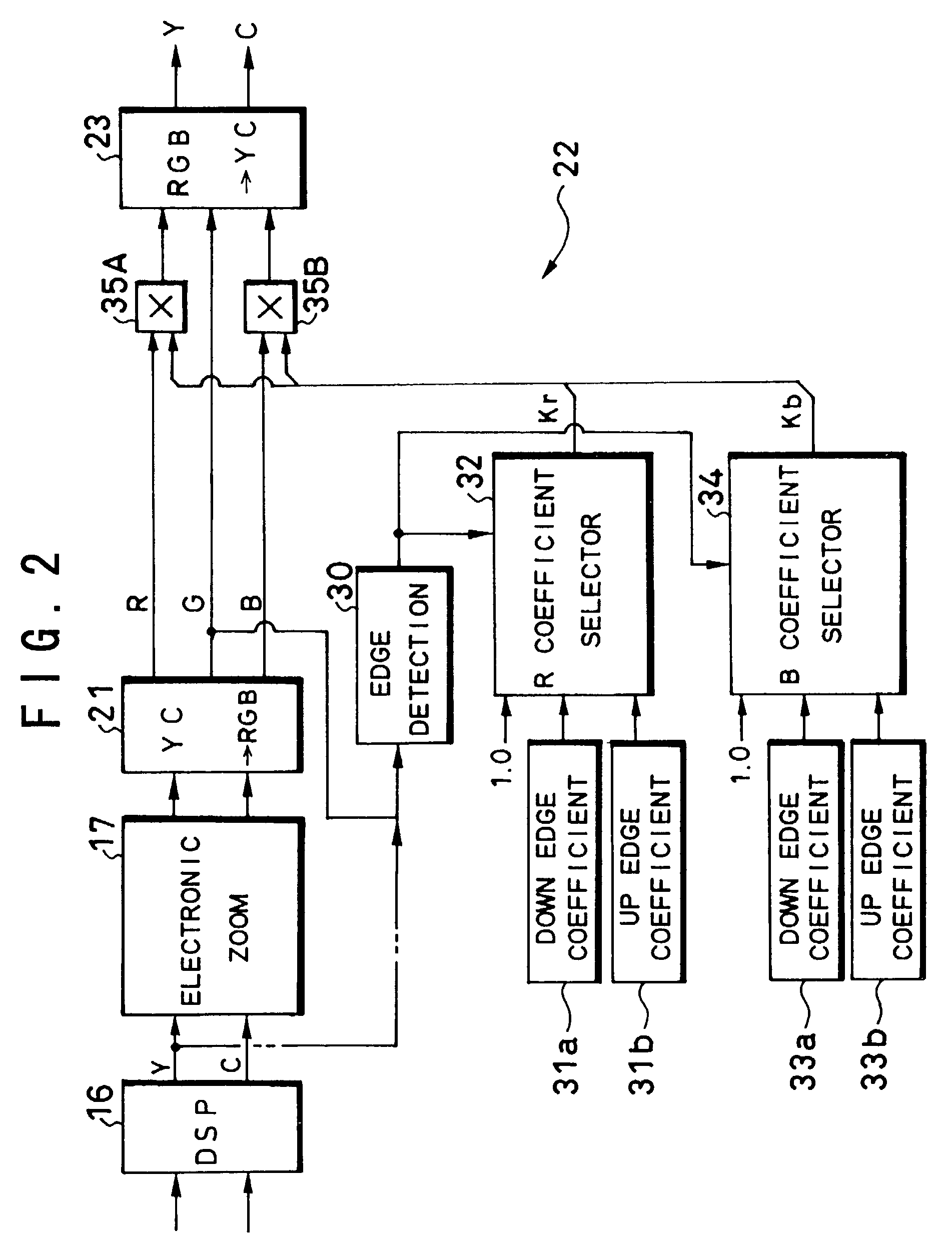
[0023]FIG. 1 shows configurations of a scope and processor unit (color signal processing circuit) in an electronic endoscope according to a first embodiment, FIG. 2 shows a configuration related to blood vessel highlighting of this electronic endoscope and though not shown in these drawings, this electronic endoscope is also provided with a light source unit, a monitor and a recorder, etc. and adopts, for example, a synchronous system as an image pickup system. In FIG. 1, a CCD 10 which is an image pickup element, is provided at a tip of the scope and this CCD 10 captures an image of an object through color filters on a pixel-by-pixel basis (e.g., Mg (magenta), G (green), Cy (cyan) and Ye (yellow)). That is, when light from the above-described light source unit is irradiated from the tip of the scope onto the object through a light guide, the image of this object is taken by the CCD 10. Furthermore, if an objective optical system with a built-in power scaling movable lens is provide...

second embodiment

[0038]FIG. 4 shows a main configuration of an electronic endoscope according to a second embodiment and the rest of the configuration except that shown in this FIG. 4 is the same as that in FIG. 1. A video signal is supplied to a DSP 116 in FIG. 4 through an A / D converter 15. This DSP 116 forms a Y (brightness) signal and forms color difference signals of R (red)-Y and B (blue)-Y by applying color conversion operations to signals obtained through various color filters of Mg, G, Cy and Ye. Then, the second embodiment performs processing to clearly display blood vessels as specific objects using these R-Y signal and B-Y signal.

[0039]That is, this embodiment is provided with a phase detection circuit 118 that inputs the above R-Y signal and B-Y signal and detects the phases of these signals, a reference value setting circuit 120 that outputs θ1 which is the phase of the blood vessel color (to be exact, θ1 with tolerance of ±α) as a reference value, a comparator 122 that compares the ph...


PUM


Abstract

In an electronic endoscope of the present invention, an edge detection circuit detects a down edge section and an up edge section of both ends of a blood vessel in a width direction based on a G signal output from an RGB color conversion circuit, an R coefficient selector and a B coefficient selector select, for example, a coefficient smaller than 1 for the detected down edge section and select, for example, a coefficient larger than 1 for the up edge section, and a multiplier multiplies an R signal and a B signal by these coefficients. As a result, both ends of the blood vessel are highlighted with a left end part expressed blackish and a right end part expressed reddish, making it possible to clearly display blood vessels in mucous membranes on a monitor. It is also possible to detect phases on a coordinate system where an R-Y signal is set on a vertical axis and a B-Y signal is set on a horizontal axis, compare these phases with reference phase θ1 of blood vessel colors and extract signals of blood vessel colors.

Description

BACKGROUND OF THE INVENTION[0001]This application claims the priority of Japanese Patent Applications No. 2002-21076 filed on Jan. 30, 2002 and No.2001-295271 filed on Sep. 27, 2001 which are incorporated herein by reference.[0002]1. Field of the Invention[0003]The present invention relates to an electronic endoscope, and more particularly, to image processing of an electronic endoscope capable of displaying blood vessels inside the body of an examinee in an easily viewable condition.[0004]2. Description of the Related Art[0005]An electronic endoscope irradiates an object under observation with illuminating light to capture an image thereof through an objective optical system, takes in the image using an image pickup element such as a CCD (Charge Coupled Device) and displays this object image on a monitor, etc. In recent years, this type of electronic endoscope incorporates a power scaling mechanism in the above-described objective optical system and displays the optically magnified...

Claims


Application Information

Patent Timeline
IPC IPC(8): H04N7/18A61B1/04A61B1/045
CPCA61B1/00009H04N7/183A61B1/045A61B1/0638A61B1/000094
Inventor HIGUCHI, MITSURUNEGISHI, KEIICHIAYAME, DAISUKEABE, KAZUNORITAKEUCHI, SHINJI
Owner FUJI PHOTO OPTICAL CO LTD
Why Eureka
Try Eureka