
Microfabricated rubber microscope using soft solid immersion lenses

a microfabricated, rubber technology, applied in the field of microscopes, can solve the problems of low magnification and spherical aberration of original design, spoilage of numerical aperture gains, and difficulty in manufacturing sils, and achieve the effect of higher light gathering ability

Inactive Publication Date: 2006-05-09
CALIFORNIA INST OF TECH
View PDF48 Cites 111 Cited by
  • Summary
  • Abstract
  • Description
  • Claims
  • Application Information

AI Technical Summary

Problems solved by technology

However, the original design suffered from low magnification and spherical aberration, defects that were not corrected until the nineteenth century when improved lens designs by Lister and Abbe came into use.
Modern high performance optical microscopes still use a combination of optical elements which are made by laborious grinding techniques.
However, these methods are hampered by the existence of an interface between the lens and the storage media, which spoils some of the numerical aperture gains.
SILs are difficult to manufacture, which heretofore has been an important limitation that has hampered their widespread adoption.
Although there has been some progress with both conventional and microfabrication technology to make the lower performance hemispherical SILs, the high performance “Weierstrass”-type SIL still requires hand grinding and polishing due to its highly undercut features.
However, attempts to mold smaller lenses that would be compatible with microfabricated applications encounter fundamental problems: the surface tension of the PDMS causes it to creep on the positive mold.

Method used


Image

  • Microfabricated rubber microscope using soft solid immersion lenses
  • Microfabricated rubber microscope using soft solid immersion lenses
  • Microfabricated rubber microscope using soft solid immersion lenses

Examples


Embodiment Construction

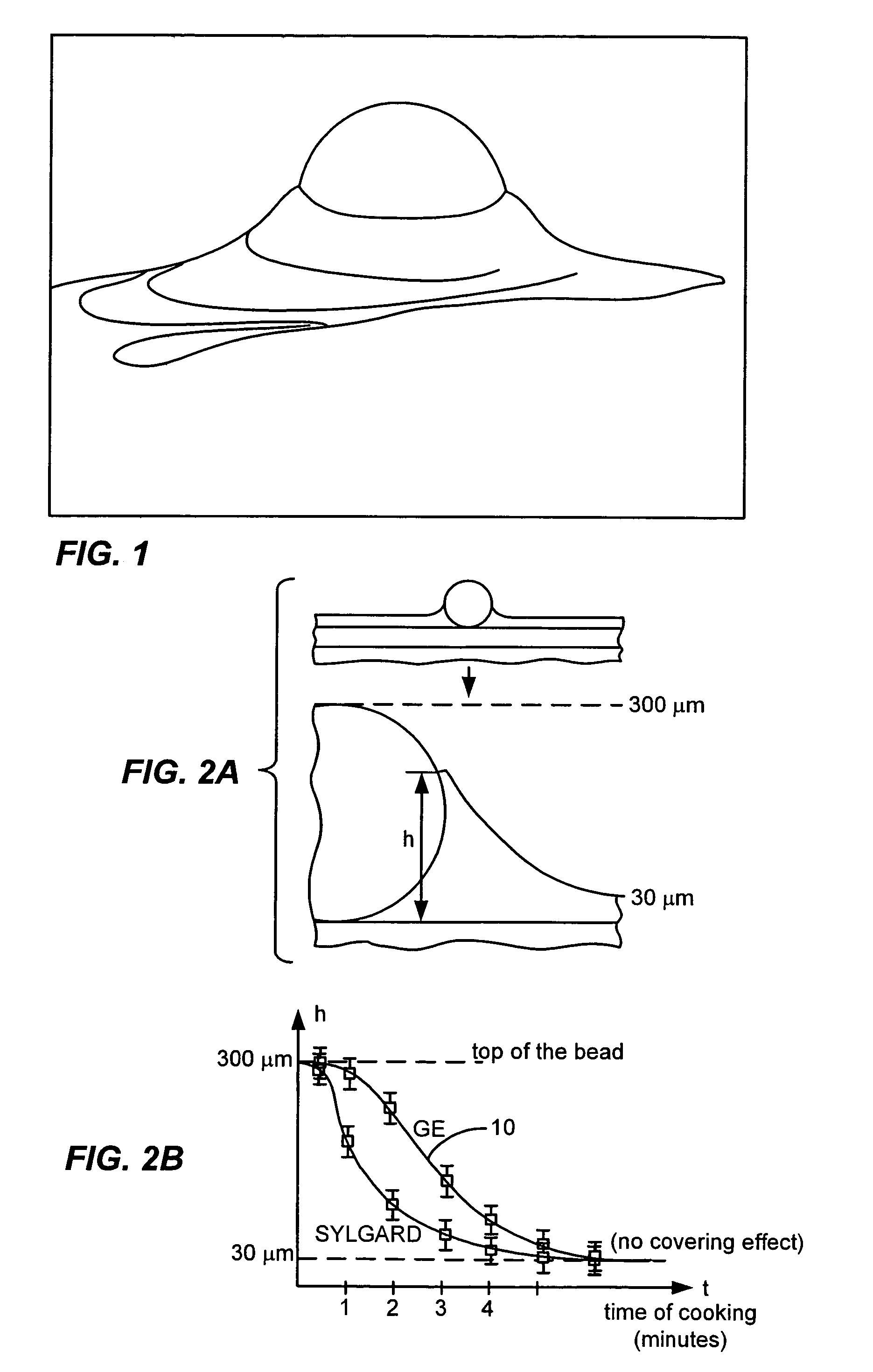
[0025]Using the techniques of soft lithography as disclosed herein, small solid immersion lenses (SILs) suitable for microscopy can be made that range in size from less than 150 microns to 10 millimeters, and such SILs have been made successfully. Referring to FIG. 1, there is shown an image of a 150 micron bead in a mold according to the invention. The mold material wicks up around the bead due to surface tension. However, the height of the mold due to such creep can be accurately correlated to pre-curing of the mold material of interest, such as General Electric RTV or Sylgard PDMS, both of which can also be used as SIL material. This correlation can be used to calibrate mold depth to cooking time.

[0026]FIG. 2B is a graph illustrating the calibration of cooking time at 80° C. for two materials, the top curve 10 being for GE RTV and the bottom curve being for Sylgard PDMS. From this curve, it can be determined that for a mold depth of h=R(1+1 / n), in this case a 150 micron sphere, t...


PUM

PropertyMeasurementUnit
sizeaaaaaaaaaa
sizeaaaaaaaaaa
sizesaaaaaaaaaa

Abstract

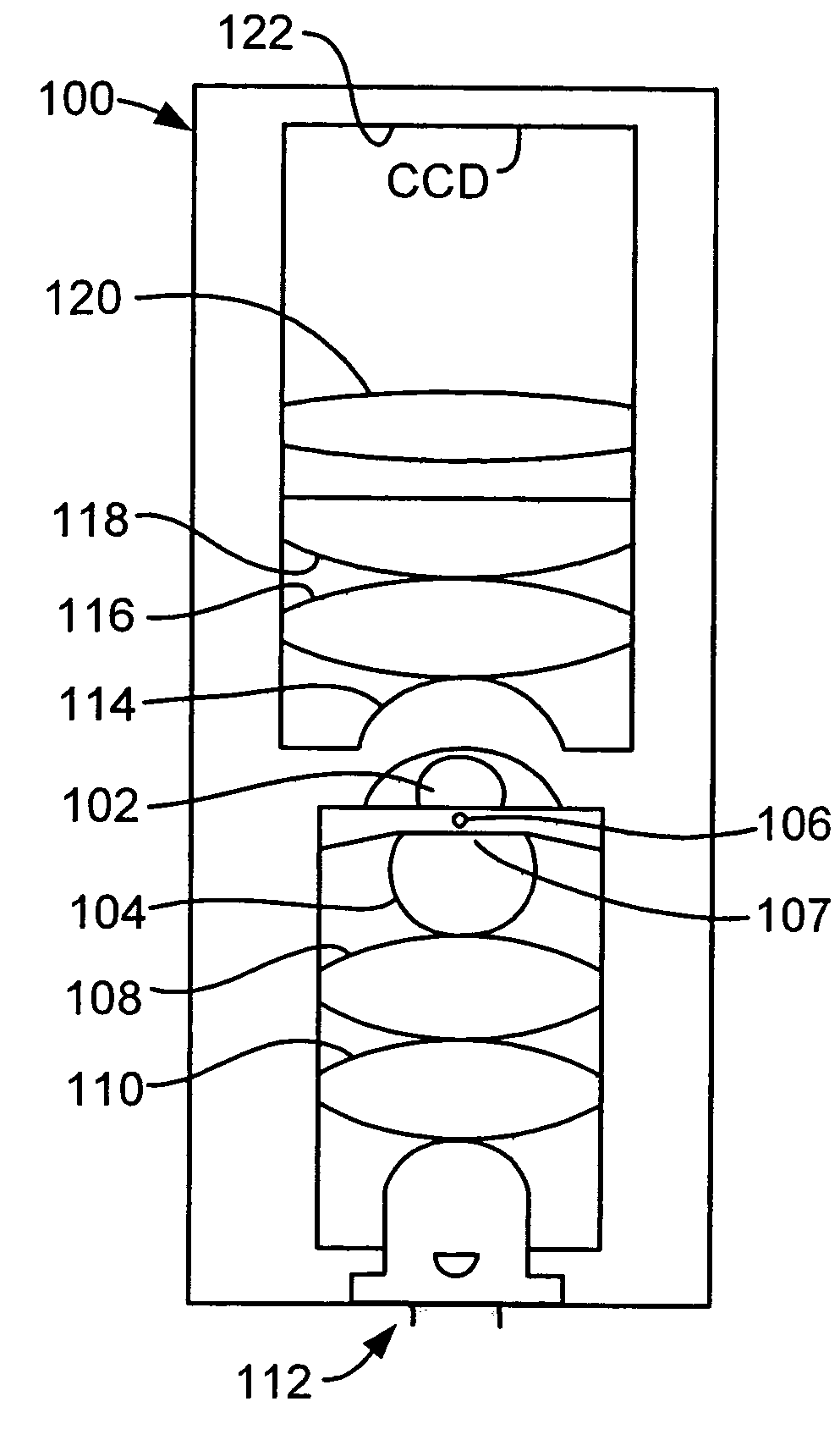
Soft lithography with surface tension control is used to microfabricate extremely efficient solid immersion lenses (SILs) out of rubber elastomeric material for use in microscope type applications. In order to counteract the surface tension of the mold material in a negative mold that causes creep on a positive mold, material such as RTV is partially cured before use in order to allow the reticulation of polymer chains to change the viscosity of the uncured material in a controllable manner. In a specific embodiment, the techniques of soft lithography with surface tension control are used to make molded SILs out of the elastomer polydimethylsiloxane. The lenses achieve an NA in the range of 1.25. The principle of compound lens design is used to make the first compound solid immersion lens, which is corrected for higher light gathering ability and has a calculated NA=1.32. An important application of these lenses is integrated optics for microfluidic devices, specifically in a handheld rubber microscope for microfluidic flow cytometry.

Description

CROSS-REFERENCES TO RELATED APPLICATIONS[0001]The instant nonprovisional patent application claims priority from U.S. provisional patent Application No. 60 / 494,416, filed Aug. 11, 2003. This previously filed provisional patent application is hereby incorporated by reference for all purposes.STATEMENT AS TO RIGHTS TO INVENTIONS MADE UNDER FEDERALLY SPONSORED RESEARCH OR DEVELOPMENT[0002]This invention was made with government support under CTS-0088649 awarded by the National Science Foundation and MDA972-00-1-0019 by DARPA. The government has certain rights in the invention.REFERENCE TO A “SEQUENCE LISTING,” A TABLE, OR A COMPUTER PROGRAM LISTING APPENDIX SUBMITTED ON A COMPACT DISK[0003]Not ApplicableBACKGROUND OF THE INVENTION[0004]This invention relates to microscopes, and more particularly to twin lens microscopes having elastomeric lenses and methods for making the same.[0005]The invention of the compound (twin lens) microscope by Zacharias and Hans Janssen dates from the beginn...

Claims


Application Information

Patent Timeline
Patent Type & Authority Patents(United States)
IPC IPC(8): G02B21/02G02B1/04G02B21/00G02B21/33
CPCG02B1/041G02B21/0008G02B21/33C08L83/04
Inventor QUAKE, STEPHEN R.GAMBIN, YANNLEGRAND, OLIVER
Owner CALIFORNIA INST OF TECH
Learn More