Tunable laser source

a laser source and tunable technology, applied in the direction of laser details, optical resonator shape and construction, semiconductor lasers, etc., can solve the problems of large size of the entire light source, wavelength error occurs, etc., and achieve the effect of miniaturizing the light source, smooth rotation, and suppressing the wavelength error with respect to the influence of temperature chang

Inactive Publication Date: 2006-05-09
YOKOGAWA ELECTRIC CORP
View PDF13 Cites 0 Cited by
  • Summary
  • Abstract
  • Description
  • Claims
  • Application Information

AI Technical Summary

Benefits of technology

[0020]An object of the invention is to provide a tunable laser source in which a wavelength error with respect to influence of a temperature change can be suppressed without using a heat insulation structure.
[0023]According to the tunable laser source, the optical base thermally expands or contracts, and the feed screw thermally expands or contracts in a degree larger than the optical base, while a point where the feed screw is at a predetermined position with respect to the optical base is set as a reference point. Even when the motor is not rotated, the mirror arm is rotated in a direction along which a variation of the length of the external resonator is corrected, via the first nut and the flat spring in accordance with the thermal expansion or contraction of the feed screw. As a result, a wavelength error with respect to influence of a temperature change can be suppressed without using a heat insulation structure, and the light source can be miniaturized.
[0024]The first nut performs a linear motion, and the mirror arm performs a rotary motion centered at the rotation center. However, the flat spring couples the first nut with the second arm portion of the mirror arm. When the flat spring is deformed, therefore, the linear force of the first nut can be transmitted to the rotational force of the mirror arm without applying undue force to the mirror arm. As a result, the mirror arm can be smoothly rotated.
[0025]Further, when the optical base thermally expands, the first nut thermally expands in a degree larger than the feed screw, and hence the inner diameter is increased. Since the compression spring is disposed between the first and second nuts, the compression spring always pushes the first nut toward the motor. Therefore, the mirror arm is rotated via the flat spring in a direction along which a variation of the length of the external resonator is corrected (specifically, in a direction along which the length of the external resonator is shortened). Consequently, a wavelength error with respect to influence of a temperature change can be further suppressed without using a heat insulation structure.

Problems solved by technology

Consequently, the positional relationships of the optical amplifier 10, the wavelength selection section 20, and the mirror arm 31 which are arranged on the optical base are varied, and the length of the external resonator is changed, thereby producing a problem in that a wavelength error occurs.
However, the size of the entire light source is very large.

Method used


Image

  • Tunable laser source
  • Tunable laser source
  • Tunable laser source

Examples


first embodiment

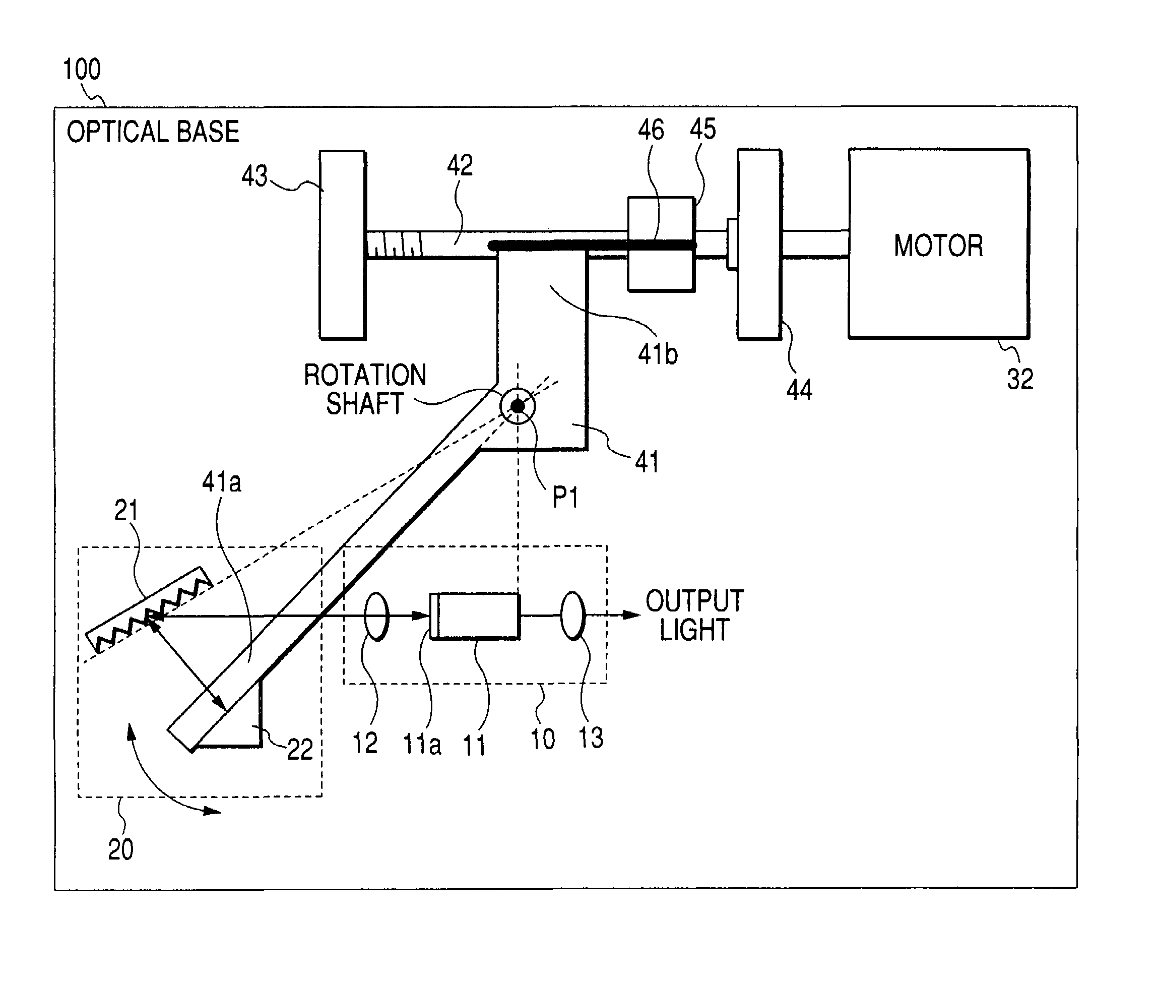
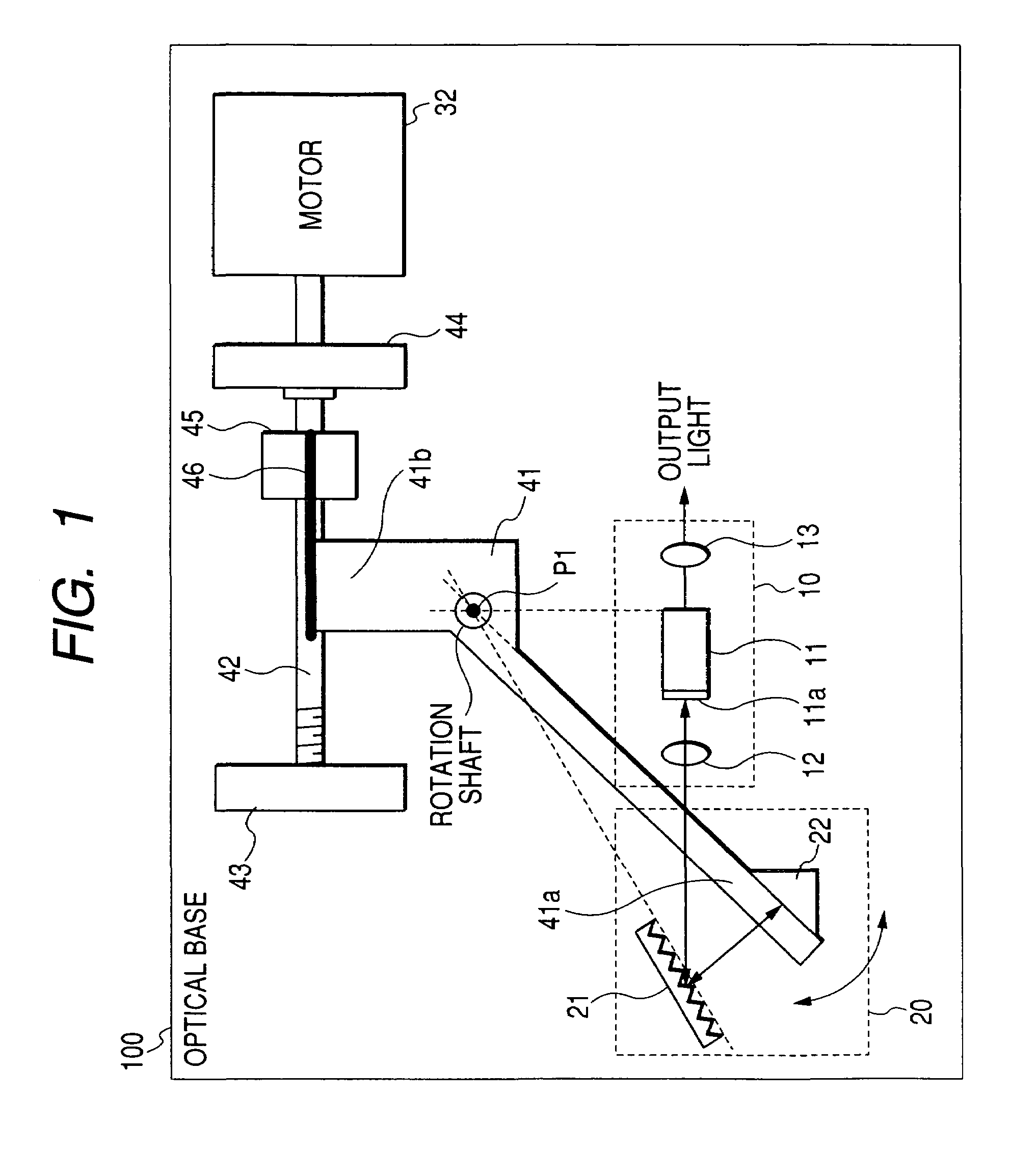
[0032]FIG. 1 is a diagram showing the configuration of a first embodiment of the invention. The components which are identical with those of FIG. 5 are denoted by the same reference numerals, and their description is omitted. In FIG. 1, the components 11 to 13 of the optical amplifier 10, the diffraction grating 21, and the motor 32 are fixed onto an optical base 100. A mirror arm 41 is disposed in place of the mirror arm 31. The rotation shaft of the mirror arm 41 is disposed at the rotation of the wavelength selection mirror 22. A first arm portion 41a and a second arm portion 41b elongate from the rotation shaft to form a substantially V-like shape. The wavelength selection mirror 22 is fixed to the first arm portion 41a.

[0033]A feed screw 42 is disposed in place of the screw 33. The tension spring 34 is removed away. Holders 43, 44 which hold the feed screw 42 are newly disposed, and fixed to the optical base 100. In the feed screw 42, one end is held by the holder 44 and recei...

second embodiment

[0046]FIG. 3 is a diagram showing the configuration of a second embodiment of the invention. The components which are identical with those of FIG. 1 are denoted by the same reference numerals, and their description is omitted. The optical base 100, the optical amplifier 10, and the diffraction grating 21 are not shown. Referring to FIG. 3, a second nut 47 which is feedably fitted to the feed screw 42, and which is disposed on the other end side of the feed screw 42 with respect to the first nut 45 is newly disposed. The coefficient of thermal expansion of the first nut 45 is larger than that of the feed screw 42.

[0047]Furthermore, a plate 48 which couples the second nut 47 with the first nut 45 is newly disposed. The plate 48 is fixed to the first nut 45 by screws which are not shown, and contacted with the second nut 47 to prevent the second nut from rotating. A coil-like compression spring 49 is newly disposed between the second nut 47 and the first nut 45. The outer periphery of ...


PUM


Abstract

A tunable laser source of a Littman arrangement type has a wavelength selection mirror rotating around a position where a mode hop is suppressed in a wavelength variation, a feed screw receiving a driving force of a motor at one end to be rotated, in which another end is disposed at a predetermined position, and which is larger in coefficient of thermal expansion than the optical base, a first nut feedably fitted to the feed screw, a flat spring in which one end is fixed to the first nut; and a mirror arm having a rotation shaft disposed at a rotation center of the wavelength selection mirror, and first and second arm portions formed in a V-like shape and elongating from the rotation shaft. The wavelength selection mirror is fixed to the first arm portion, and another end of the flat spring is fixed to the second arm portion.

Description

CROSS-REFERENCE TO RELATED APPLICATIONS[0001]This application is based upon and claims the benefit of priority from the prior Japanese Patent Applications No. 2004-271408, filed on Sep. 17, 2004, the entire contents of which are incorporated herein by reference.BACKGROUND OF THE INVENTION[0002]1. Field of the Invention[0003]The invention relates to a tunable laser source of a Littman arrangement type, including a semiconductor laser and a diffraction grating which are fixed to an optical base, and a wavelength selection mirror which rotates around a position, as a rotation center, where a mode hop is suppressed at a time of a wavelength variation. The invention particularly relates to a tunable laser source in which a wavelength error with respect to influence of a temperature change can be suppressed without using a heat insulation structure.[0004]2. Description of the Related Art[0005]FIG. 5 shows the configuration of an external resonator type tunable laser source as a related ar...

Claims


Application Information

Patent Timeline
Patent Type & Authority Patents(United States)
IPC IPC(8): H01S3/10H01S3/08
CPCH01S5/141H01S5/02H01S5/143H01S3/1055
Inventor MIYAKI, SHOSUKE
Owner YOKOGAWA ELECTRIC CORP
Why Eureka
Try Eureka