Automatically populated display regions for discovered access points and stations in a user interface representing a wireless communication network deployed in a physical environment

a wireless communication network and user interface technology, applied in the field of user interface representations of wireless communication systems, can solve the problems of difficult to visually locate the new device in the display, difficult for the user to quickly distinguish between these device types, and difficult to distinguish between access points and stations within a wireless network

Active Publication Date: 2006-05-09
AI-CORE TECH LLC
View PDF3 Cites 129 Cited by
  • Summary
  • Abstract
  • Description
  • Claims
  • Application Information

AI Technical Summary

Benefits of technology

[0007]Thus there is disclosed a system for representing discovered access points and stations in a user interface showing a deployed wireless network physical environment. The disclosed system allows a user to conveniently identify access points and stations as they are automatically discovered, and to conveniently place the access point and station representations at locations within a representation of a physical environment.

Problems solved by technology

Graphical representations of access points and stations may be similar or identical, making it difficult for the user to quickly distinguish between these device types.
Users accordingly find it difficult to distinguish between access points and stations within a wireless network.
Similarly, when a network device is discovered within the network, the visual representation for that device may be initially displayed directly within a relatively complex logical network map, making it difficult for the user to visually locate the new device in the display.
Moreover, after a device has been automatically discovered, the user cannot conveniently place the representation of that device within a representation of the wireless network's physical environment using existing systems.

Method used


Image

  • Automatically populated display regions for discovered access points and stations in a user interface representing a wireless communication network deployed in a physical environment
  • Automatically populated display regions for discovered access points and stations in a user interface representing a wireless communication network deployed in a physical environment
  • Automatically populated display regions for discovered access points and stations in a user interface representing a wireless communication network deployed in a physical environment

Examples


Embodiment Construction

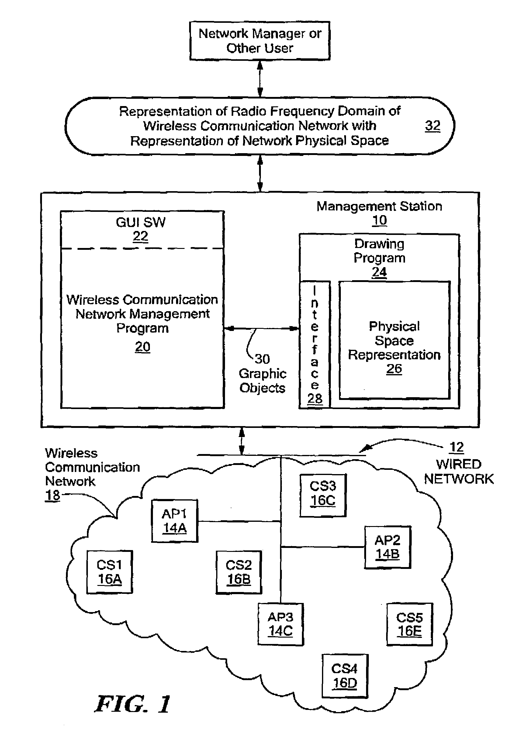
[0032]As shown in FIG. 1, an illustrative embodiment of the disclosed system includes a wireless communication network management software program 20 and a separate drawing software program 24 executing on a management station 10. The management station 10 may, for example, consist of any specific type of computer system, including one or more processors operable to execute program code stored in a computer program memory or other type of computer program storage device, and having a number of input / output devices and interfaces. The management station 10 is communicably coupled to a wired network 12, which in turn is coupled to a number of wireless access point devices 14, shown for purposes of illustration as access points AP114A, AP214B, and AP314C. The access point devices 14 provide wireless access to the wired network 12 to client station devices 16. The client station devices 16 are shown for purposes of illustration as client stations CS116A, CS216B, CS316C, CS416D, and CS51...


PUM


Abstract

A system for providing automatically populated display regions showing discovered access points and stations in a user interface representing a wireless communication network deployed in a physical environment. A generated user interface includes a first display region in which access point representations are displayed as corresponding access points are automatically discovered within the wireless network, and a second display region in which station representations are displayed as corresponding stations are automatically discovered within the wireless network. The first and second display regions are provided external to another display region, referred to as the “physical space” display region, in which is shown a representation of the physical space in which the wireless network is deployed. As the access point and station representations appear in the first display region and second display region, the user can manipulate them, for example by drag and drop operations using a computer mouse, in order to place them appropriately in the physical space display region. In response, the disclosed system superimposes the access point and station representations over the physical space representation. The access point and station representations can subsequently be similarly repositioned by the user within the physical space representation.

Description

FIELD OF THE INVENTION[0001]The disclosed system relates generally to user interface representations of wireless communication systems, and more specifically to a system and method for providing automatically populated display regions for discovered access points and stations in a user interface representing a wireless communication network deployed in a physical environment.BACKGROUND OF THE INVENTION[0002]Wireless communication networks are becoming increasingly common for interconnecting many types of electronic devices. Computer systems of all sizes, personal digital assistants, input / output devices, entertainment system components and other types of home appliances, are all examples of client station devices that are candidates for interconnection using a wireless communication network. Various specific wireless communication protocols have been developed. Examples of existing wireless communication protocols may be found in the family of standards for wireless Local Area Netwo...

Claims


Application Information

Patent Timeline
Patent Type & Authority Patents(United States)
IPC IPC(8): H04Q7/20H04W16/18H04W16/22H04W24/00H04W40/00H04W88/02H04W88/08
CPCH04L41/12H04L41/22H04W16/225H04W24/00H04W16/18H04L41/0213H04L41/0896H04W88/08H04W40/00H04W88/02
Inventor PFISTER, ROGER
Owner AI-CORE TECH LLC
Why Eureka
Try Eureka