Subcutaneous implantable cardioverter-defibrillator employing a telescoping lead

a technology of implantable cardioverter and telescoping lead, which is applied in the direction of external electrodes, internal electrodes, therapy, etc., can solve the problems of no practical use, no system use, and no practical us

Inactive Publication Date: 2006-05-09
CAMERON HEALTH
View PDF138 Cites 127 Cited by
  • Summary
  • Abstract
  • Description
  • Claims
  • Application Information

AI Technical Summary

Problems solved by technology

This system is far more complicated to use than current ICD systems using transvenous lead systems together with an active can electrode and therefore it has no practical use.
It has in fact never been used because of the surgical difficulty of applying such a device (3 incisions), the impractical abdominal location of the generator and the electrically poor sensing and defibrillation aspects of such a system.
ICDs are very effective at treating V-Fib, but are therapies that still require significant surgery.
In addition, chronic transvenous lead systems, their reimplantation and removals, can damage major cardiovascular venous systems and the tricuspid valve, as well as result in life threatening perforations of the great vessels and heart.
Consequently, use of transvenous lead systems, despite their many advantages, are not without their chronic patient management limitations in those with life expectancies of >5 years.
The problem of lead complications is even greater in children where body growth can substantially alter transvenous lead function and lead to additional cardiovascular problems and revisions.
Moreover, transvenous ICD systems also increase cost and require specialized interventional rooms and equipment as well as special skill for insertion.
However, an AED must be used by another individual, not the person suffering from the potential fatal rhythm.
Because >75% of cardiac arrests occur in the home, and over half occur in the bedroom, patients at risk of cardiac arrest are often alone or asleep and can not be helped in time with an AED.

Method used


Image

  • Subcutaneous implantable cardioverter-defibrillator employing a telescoping lead
  • Subcutaneous implantable cardioverter-defibrillator employing a telescoping lead
  • Subcutaneous implantable cardioverter-defibrillator employing a telescoping lead

Examples


Embodiment Construction

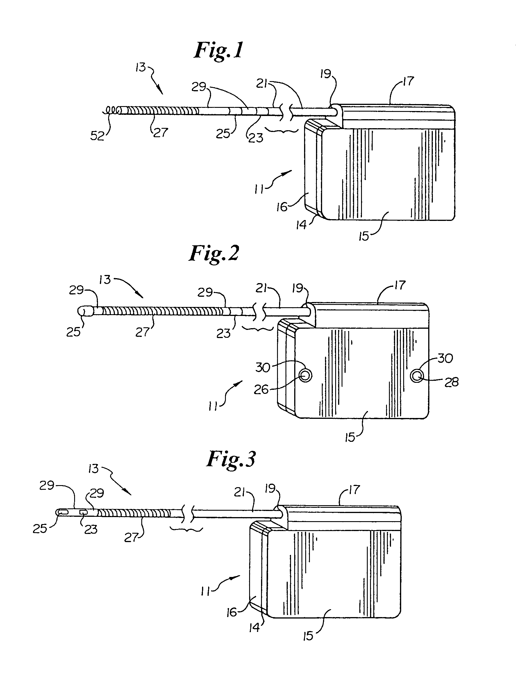
[0051]Turning now to FIG. 1, the S-ICD of the present invention is illustrated. The S-ICD consists of an electrically active canister 11 and a subcutaneous electrode 13 attached to the canister. The canister has an electrically active surface 15 that is electrically insulated from the electrode connector block 17 and the canister housing 16 via insulating area 14. The canister can be similar to numerous electrically active canisters commercially available in that the canister will contain a battery supply, capacitor and operational circuitry. Alternatively, the canister can be thin and elongated to conform to the intercostal space. The circuitry will be able to monitor cardiac rhythms for tachycardia and fibrillation, and if detected, will initiate charging the capacitor and then delivering cardioversion / defibrillation energy through the active surface of the housing and to the subcutaneous electrode. Examples of such circuitry are described in U.S. Pat. Nos. 4,693,253 and 5,105,810...


PUM


Abstract

One embodiment of the present invention provides an implantable cardioverter-defibrillator for subcutaneous positioning between the third rib and the twelfth rib within a patient, the implantable cardioverter-defibrillator including a housing including a first electrode; a telescoping lead assembly including a second electrode, wherein the telescoping lead assembly is electrically and mechanically coupled to the housing; and an electrical circuit located within and electrically coupled to the housing.

Description

CROSS-REFERENCE TO RELATED APPLICATIONS[0001]The present application is a continuation-in-part of each of the following applications: U.S. patent application entitled “SUBCUTANEOUS ONLY IMPLANTABLE CARDIOVERTER-DEFIBRILLATOR AND OPTIONAL PACER,” having Ser. No. 09 / 663,607, filed Sep. 18, 2000, now U.S. Pat. No. 6,721,597, U.S. patent application entitled “UNITARY SUBCUTANEOUS ONLY IMPLANTABLE CARDIOVERTER-DEFIBRILLATOR AND OPTIONAL PACER,” having Ser. No. 09 / 663,606, filed Sep. 18, 2000, now U.S. Pat. No. 6,647,292, U.S. patent application Ser. No. 09 / 940,599 entitled “CANISTER DESIGNS FOR IMPLANTABLE CARDIOVERTER-DEFIBRILLATOR,” filed Aug. 27, 2001, now U.S. Pat. No. 6,950,705, U.S. patent application Ser. No. 09 / 940,283 entitled “DUCKBILL-SHAPED IMPLANTABLE CARDIOVERTER-DEFIBRILLATOR AND METHOD OF USE,” filed August 2001, pending, U.S. patent application Ser. No. 09 / 940,377 entitled “METHOD OF INSERTION AND IMPLANTATION OF IMPLANTABLE CARDIOVERTER-DEFIBRILLATOR CANISTERS,” filed A...

Claims


Application Information

Patent Timeline
Patent Type & Authority Patents(United States)
IPC IPC(8): A61N1/375A61NA61N1/05A61N1/39
CPCA61N1/3956
Inventor ERLINGER, PAUL J.BARDY, GUST H.
Owner CAMERON HEALTH
Why Eureka
Try Eureka