Bone supported vascular access port

a vascular access port and bone support technology, applied in the direction of intravenous devices, infusion needles, other medical devices, etc., can solve the problems of port stability within the body after being placed, reducing the propensity to flip, so as to facilitate the removal of the port

Inactive Publication Date: 2007-08-02
GLENN BRADLEY J
View PDF80 Cites 81 Cited by
  • Summary
  • Abstract
  • Description
  • Claims
  • Application Information

AI Technical Summary

Benefits of technology

[0008]A subcutaneous implantable vascular access port is provided according to this invention which is particularly adapted to be affixed to a bone of the patient. For instance, the port could be configured to be coupled to the clavicle of the patient. Initially, a hole is formed in the bone at the implantation site for the port. The port is configured so that it can be placed within this hole in the bone and held securely within the hole in the bone. For instance, an outer surface of the port can be fitted with a series of threads which engage sides of the hole in the bone to secure the port to the bone. Such threads can both support the port during implantation and also facilitate removal of the port when it is no longer needed.

Problems solved by technology

One limitation to the development of smaller profile ports is the problem of port stability within the body after being placed.
Ports in use currently have a propensity to flip-over within the body if not sutured in place, rendering them inaccessible because the septum is facing down rather than up.
The smaller the port, the greater the propensity to flip-over, and the harder it is to suture the port in place due to the smaller incision and smaller working pocket within which to suture.
While suturing can be somewhat effective, it is time consuming and not entirely reliable.
While such a configuration does allow for a slightly minimized incision size, this prior art access port is not stabilized and is thus susceptible to “flipping-over” or otherwise rotating into an undesirable position.
Another problem with prior art implantable subcutaneous vascular access ports is that in patients with low body fat, the vascular access port is often highly visible as a protrusion beneath the skin.
Such appearance is often considered to be particularly undesirable.
In other patients, it can be difficult to find the vascular access port due to the particular patient's physiology tending to excessively disguise the location of the vascular access port.

Method used


Image

  • Bone supported vascular access port
  • Bone supported vascular access port
  • Bone supported vascular access port

Examples


Embodiment Construction

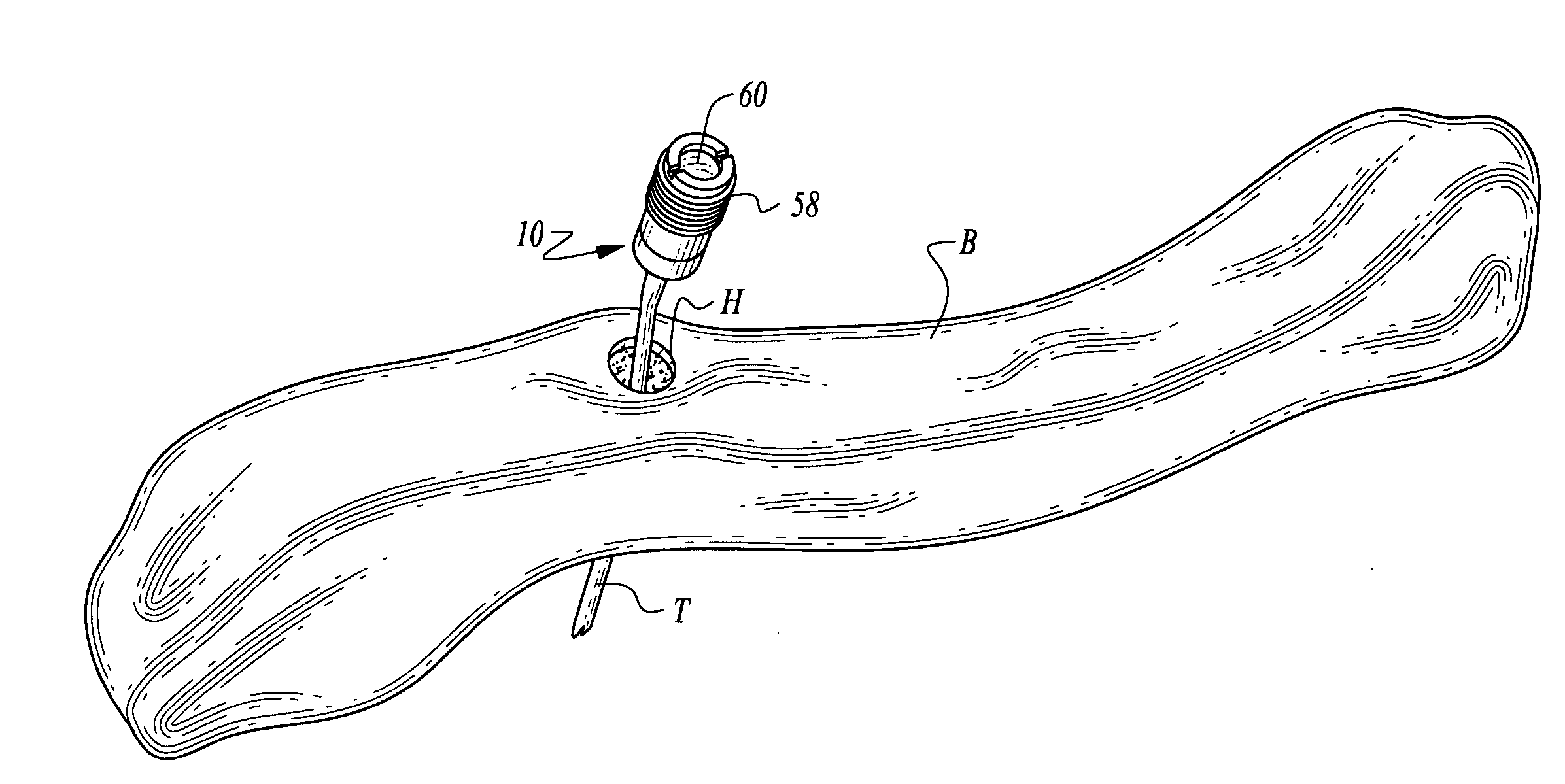
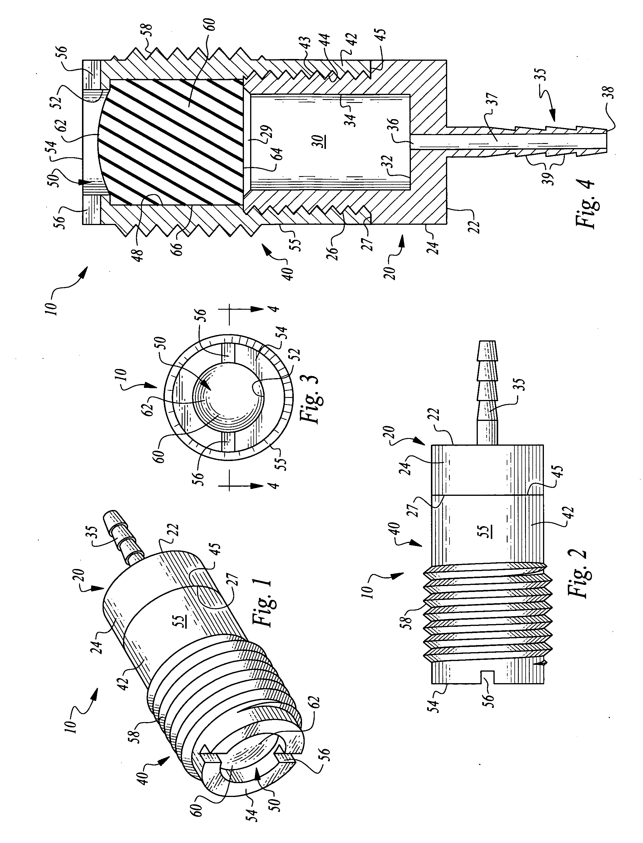
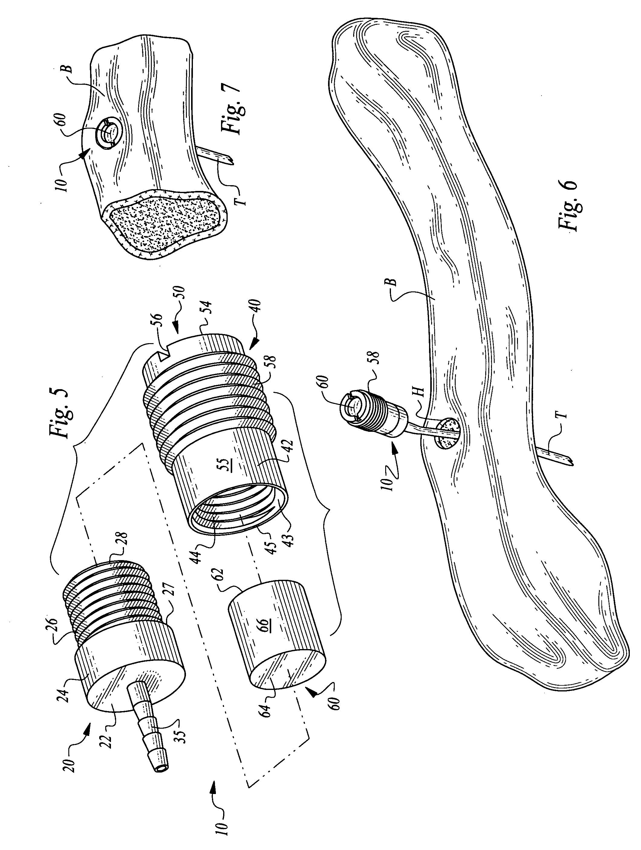
[0028]Referring to the drawings, wherein like reference numerals represent like parts throughout the various drawing figures, reference numeral 10 is directed to a bone supported vascular access port (FIGS. 6 and 7). The port 10 is configured with an outer surface 55 (FIG. 1) which can fit within a hole H in a bone B to secure the port 10 in fixed position subcutaneously within the patient. Catheter tubing T is coupled to the port 10 for vascular access between a chamber 30 (FIG. 4) within the port 10, and into the vascular system of the patient. An aperture 50 (FIGS. 1 and 4) provides access to the chamber 30 through a septum 60 which allows a needle to pass therethrough and which can reseal multiple times after needle removal. The port 10 thus provides a securely positioned, easily findable and usable subcutaneous vascular access port which also is substantially invisible to a casual observer of the patient.

[0029]In essence, and with particular reference to FIGS. 1 and 4, basic de...


PUM


Abstract

A vascular access port is disclosed for subcutaneous implantation. The port is particularly adapted to be affixed to a bone to securely hold the port in position, to assist medical personnel in finding the port and to decrease a visibility of the port. The port has a chamber therein which is accessed by a needle through a septum adjacent the chamber. The chamber is placed into fluid communication with the vascular structure of the patient, such as through catheter tubing. The chamber is surrounded by a body with an outer surface which is preferably fitted with threads to facilitate secure but removable attachment of the port within a hole in the bone where the port is to be implanted.

Description

CROSS-REFERENCE TO RELATED APPLICATIONS[0001]This application claims benefit under Title 35, United States Code §119(e) of U.S. Provisional Application No. 60 / 762,848 filed on Jan. 30, 2006.FIELD OF THE INVENTION[0002]The following invention relates to implantable vascular access ports for implantation subcutaneously and which can receive a medication or other liquid preparation by a needle inserted through the skin and into the port, and then on into the vascular system of the patient. More particularly, this invention relates to subcutaneous implantable vascular access ports which are particularly configured to be affixed to a bone or other subcutaneous structure to provide secure placement of the access port.BACKGROUND OF THE INVENTION[0003]Subcutaneously implanted vascular access devices, or ports, have been used for many years to provide long term vascular access in patients that require frequent or periodic therapeutic infusions or blood draws. Prior art ports generally have a...

Claims


Application Information

Patent Timeline
Patent Type & Authority Applications(United States)
IPC IPC(8): A61M31/00A61M37/00
CPCA61B17/3472A61M39/0208A61M39/0247A61M39/04A61M2039/0223A61M2202/10A61M2039/0258A61M2039/0261A61M2039/027A61M2039/0276A61M2039/0279A61M2039/025
Inventor GLENN, BRADLEY J.
Owner GLENN BRADLEY J
Why Eureka
Try Eureka