Numeric control lathe and method for controlling the same

Inactive Publication Date: 2006-05-09
CITIZEN WATCH CO LTD
View PDF11 Cites 15 Cited by
  • Summary
  • Abstract
  • Description
  • Claims
  • Application Information

AI Technical Summary

Benefits of technology

[0013]Therefore, an object of the present invention is to provide a multifunction type NC lathe having a plurality of lines, improved in freedom of describing routine when a user prepares multi-line machining programs.
[0014]Another object of the present invention is to provide a multifunction type NC lathe having a plurality of lines, able to facilitate the input work and eliminate input errors when a user prepares multi-line machining programs and able to shorten the time for execution of the prepared machining programs (that is, the machining time).
[0015]A still further object of the present invention is to provide an NC unit built into such an NC lathe and facilitating the preparation of multi-line machining programs.

Problems solved by technology

Further, in this case, some NC units use specific codes for matching the timing of control among lines, so there was a tendency for the time for execution of a machining program (that is, the machining time) to become longer by the amount of the blocks describing these codes, the input work to become complicated, and input errors due to descriptive omissions to easily occur.
Therefore, the user was not given the freedom to select the line for control of the machining operation in that case.
Further, in the case of control by superposition of axes in a conventional multifunction type NC lathe, the software of general NC units was prepared using specific codes for instructing the start and end of the superposition control, so there was a tendency for the time for execution of a machining program (that is, the machining time) to become longer by the amount of the blocks describing these codes, the input work to become complicated, and input errors due to descriptive omissions to easily occur.
This prior art, however, does not solve the various problems explained above occurring when a user prepares multi-line machining programs.

Method used


Image

  • Numeric control lathe and method for controlling the same
  • Numeric control lathe and method for controlling the same
  • Numeric control lathe and method for controlling the same

Examples


Embodiment Construction

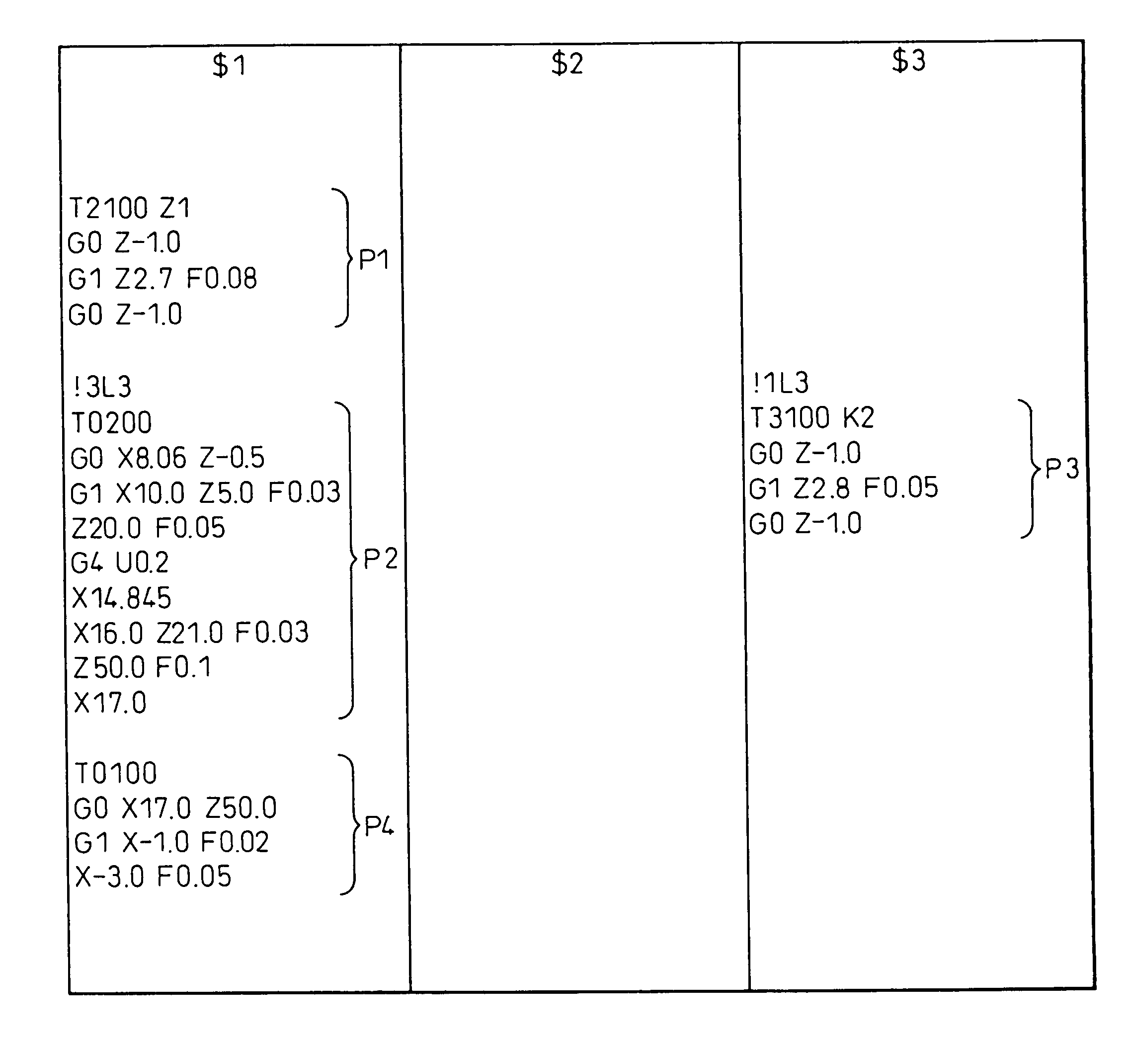
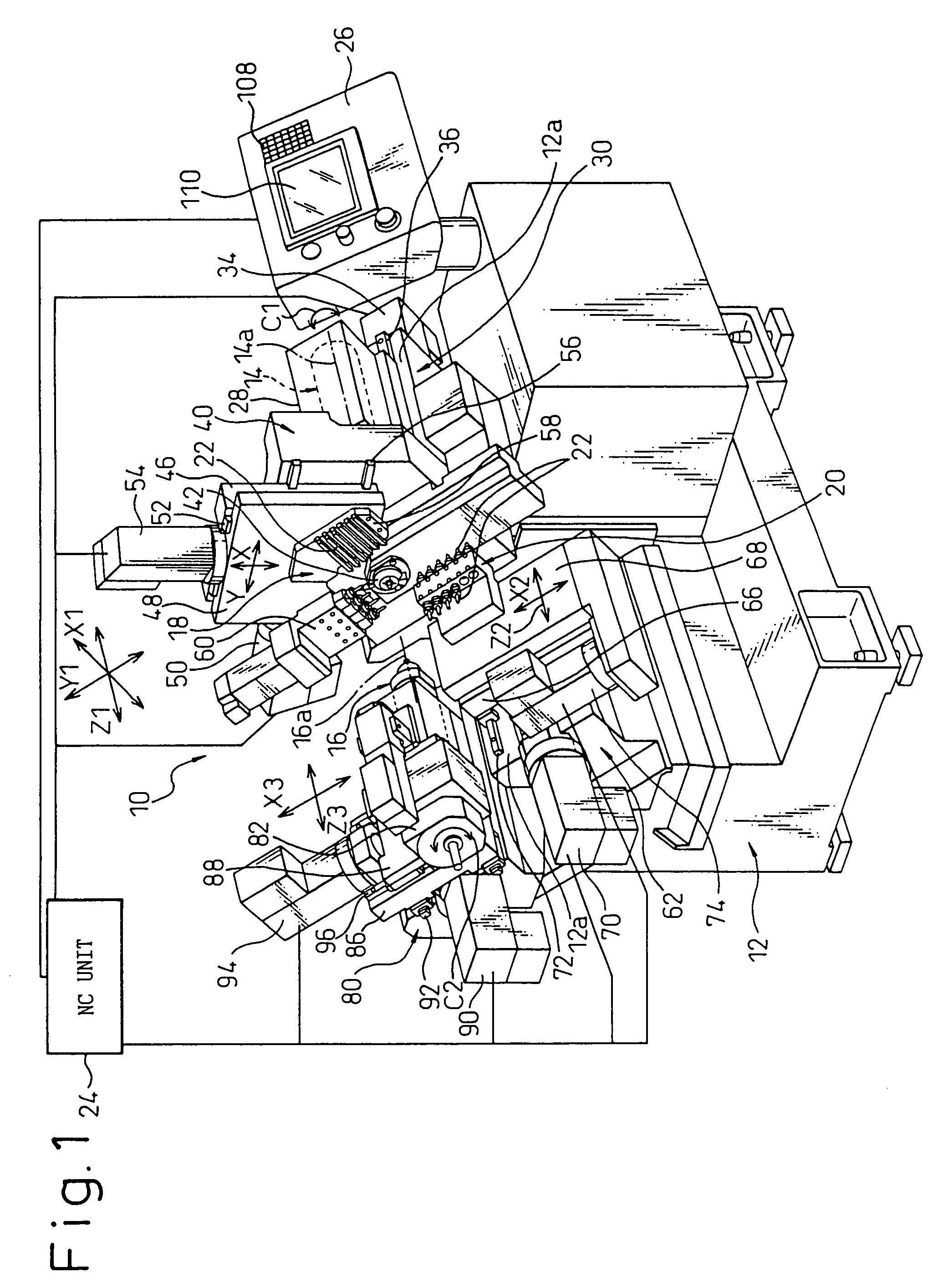
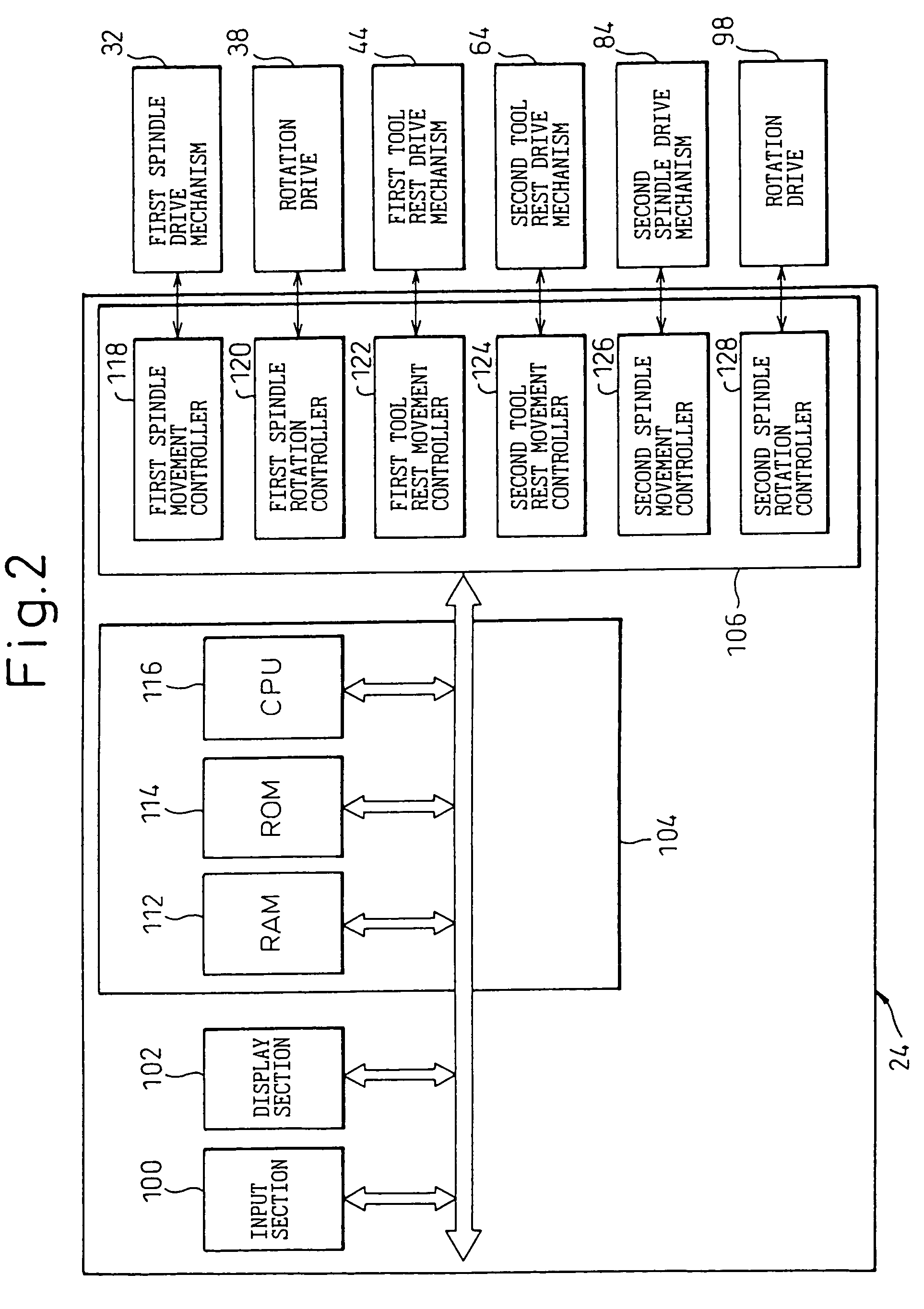
[0067]Referring to the drawings, FIG. 1 shows the overall configuration of a numerically controlled (NC) lathe 10 according to an embodiment of the present invention. The NC lathe 10 has a three-line multifunction structure carrying close together on a single lathe bed 12 two spindles 14 and 16 and two tool rests 18 and 28, and capable of performing different types of machining (for example, outer circumferential turning and boring) simultaneously on the same bar or simultaneous machining on different bars by various tools 22 including single point tools, drills, and other turning tools or milling cutters and other rotary tools.

[0068]That is, the NC lathe 10 is basically provided with a lathe bed 12; a first spindle 14 installed on the lathe bed 12, including an axis of rotation 14a, and capable of operating under control in a first line (that is, a line-1); a first tool rest 18 installed on the lathe bed 12 and capable of operating under control in the line-1 common with the first ...


PUM

PropertyMeasurementUnit
Areaaaaaaaaaaa

Abstract

A numerically controlled lathe (10) includes a control unit (24) for controlling the operations of at least one spindle (14, 16) and at least one tool rest (18, 20) on a lathe bed (12) along a plurality of control axes in a plurality of lines. The control unit (24) has an input section (100) for inputting a plurality of machining programs about a plurality of tools (22) mounted on at least one tool rest, a storage section (112) having a plurality of program-describing areas ($1, $2, $3) corresponding to the lines for describing and storing the machining programs input by the input section in the program-describing areas, and a processing section (116) for allocating the control axes to the program-describing areas in the storage section, each control axes being as a reference control axis, and for applying, to an actual control axis for controlling a machining operation relating to one designated tool designated in each machining program, the reference control axis allocated to a program-describing area freely selected from the program-describing areas to describe a machining program designating the designated tool.

Description

TECHNICAL FIELD[0001]The present invention relates to a multifunction type numerically controlled lathe including at least one spindle and at least one tool rest, which are operable under control in a plurality of paths or lines, and also to a control unit built into this numerically controlled lathe. Further, the present invention relates to a controlling method and a program-describing method of such a numerically controlled lathe.BACKGROUND ART[0002]In recent years, in the field of automatic lathes (that is, lathes able to perform automatic machining) such as numerical control lathes (hereinafter called “NC lathes”), to enable machining of much more complicatedly shaped workpieces from a bar-shaped worked material (hereinafter called a “bar”), compound or combination machining where a large number of types of tools including rotary tools are provided on a tool rest to enable diverse automatic machining such as milling in addition to turning is being promoted. Further, to shorten ...

Claims


Application Information

Patent Timeline
IPC IPC(8): G06F19/00B23B3/16G05B19/19G05B19/4155
CPCB23B3/168G05B19/19G05B19/4155G05B2219/45141G05B2219/33129G05B2219/36186G05B2219/33128G05B19/18
Inventor FUJINAWA, TADASHIISHIMURA, TOSHIO
Owner CITIZEN WATCH CO LTD
Why Eureka
Try Eureka