Field watch apparatus

Inactive Publication Date: 2008-08-07
DENSO CORP
View PDF27 Cites 57 Cited by
  • Summary
  • Abstract
  • Description
  • Claims
  • Application Information

AI Technical Summary

Benefits of technology

[0007]The field watch apparatus of the present invention acquires road images including other vehicles around the subject vehicle from the roadside capture units disposed (in a detached manner relative to the subject vehicle) in a proximity of the subject vehicle on a currently traveling road, and generates the overhead view of a subject vehicle's vicinity. Therefore, the position of the roadside capture unit is not limited relative to the

Problems solved by technology

Further, freedom of perspective setting of the roadside capture unit is improved, there

Method used


Image

  • Field watch apparatus
  • Field watch apparatus
  • Field watch apparatus

Examples


Example

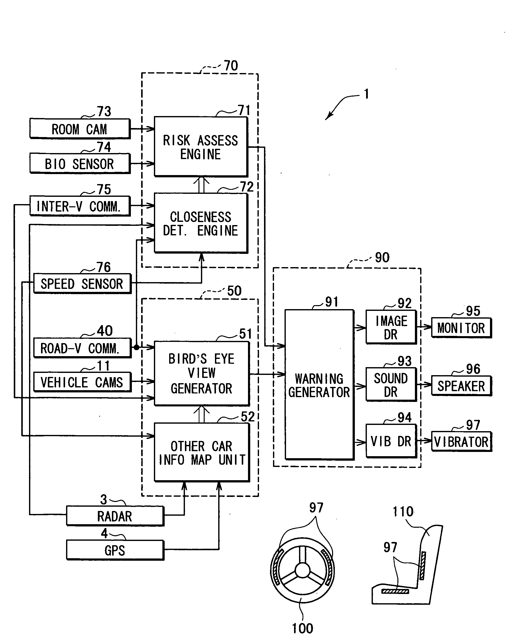
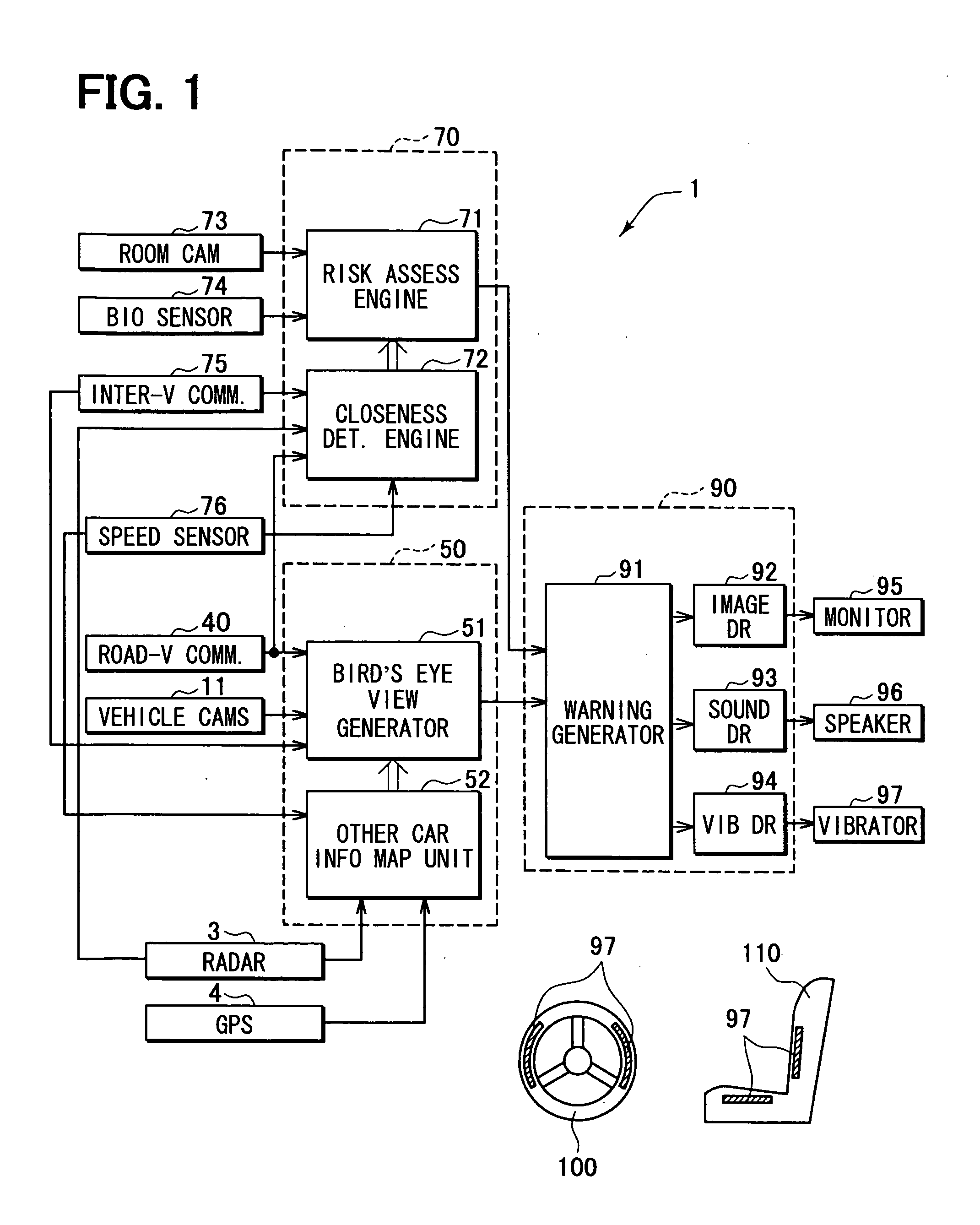
[0023]FIG. 1 is a block diagram to show an example of the electric constitution of a vehicular field watch apparatus of the present invention. The vehicular field watch apparatus 1 mainly consists of an ECU that is in charge of total control, with an image ECU 50, a risk estimate ECU 70 and a warning output control ECU 90 connected through network in the present embodiment. Each of the ECU 50, 70, 90 is constituted of a CPU, a ROM that stores software being executed by the CUP, a RAM as a work memory, and input and output (I / O) portion respectively connected by a bus. That is, those ECUs are microcomputers of well-known type.

[0024]An in-vehicle camera group 11 is connected to the image ECU 50. In addition, a road-vehicle-communication unit 40 consisting of the radio transmitter-receiver is also connected to the ECU 50 through a communication interface (not illustrated). Furthermore, to the image ECU 50, a GPS 4 for detecting a self car position as well as a radar 3 are respectively ...


PUM


Abstract

A field watch apparatus for use in a subject vehicle acquires a road image from a roadside capture unit located around the subject vehicle on a road and, based on the acquired image, generates an overhead view of a field around the subject vehicle in an intuitively recognizable manner by including a distant surrounding vehicle in the view, thereby providing a precisely understandable view of the field around the subject vehicle for the ease of satisfactorily identifying the distant surrounding vehicle without being compromised by the position of the roadside capture unit.

Description

CROSS REFERENCE TO RELATED APPLICATION[0001]This application is based on and claims the benefit of priority of Japanese Patent Application No. 2007-26951 filed on Feb. 6, 2007, the disclosure of which is incorporated herein by reference.FIELD OF THE DISCLOSURE[0002]The present disclosure generally relates to a field watch / observation apparatus for use in a vehicle.BACKGROUND INFORMATION[0003]In recent years, various techniques for watching a field around an automobile are disclosed. For example, an apparatus described in a republished patent document WO00 / 64175 (U.S. Pat. No. 7,161,616) has plural cameras on a subject vehicle that capture a field image around the subject vehicle in various angles, compose those images by shifting viewpoints for generating an overhead view of the subject vehicle, and displays the overhead view on the apparatus. Further, Japanese patent documents such as JP-A-2003-312415, JP-A-2005-5978, JP-A-2002-232948, JP-A-2006-107521, JP-A-2006-282111 disclose a ...

Claims


Application Information

Patent Timeline
IPC IPC(8): H04N7/18G01S13/89G01S13/06
CPCG01S13/89G01S13/931G01S17/023G01S17/936G01S2013/9378G01S2013/9357G01S2013/936G01S2013/9321G01S2013/9375G01S2013/9353G01S2013/93272G01S2013/9322G01S2013/93271G01S2013/9316G01S17/86G01S2013/932G01S17/931
Inventor TAUCHI, MAKIKOIGUCHI, SEINAGATA, ASAKO
Owner DENSO CORP
Why Eureka
Try Eureka