
Vibration damping device

Inactive Publication Date: 2009-03-26
TOKAI RUBBER IND LTD
View PDF0 Cites 7 Cited by
  • Summary
  • Abstract
  • Description
  • Claims
  • Application Information

AI Technical Summary

Benefits of technology

[0012]It is therefore one object of this invention to provide a vibration damping device of novel structure that can afford adequate freedom in tuning of damping characteristics.

Problems solved by technology

With a structure like that of the fluid filled, tubular vibration damping device disclosed in JP-A-2006-266438, in which the main rubber elastic body is disposed and the fluid chamber is formed in a zone defined in the diametrical direction between the inner shaft member and the outer tubular member, it will be difficult in some instances to ensure sufficiently large capacity of the fluid chambers, with the resultant anxiety of difficulty in achieving either the required vibration damping capability or the required durability.
In particular, given the increasingly smaller available vibration damping installation spaces in recent devices, reduction of the size of the vibration damping device per se has become an important issue, and this has made it more difficult to ensure a zone of sufficient size in the diametrical direction between the inner shaft member and the outer tubular member through increases in the diameter of the outer tubular member.
However, additional research conducted by the inventors in relation to the vibration damping device having the structure described above has shown that merely subjecting the rubber elastic wall of the fluid-filled unit to pressing force of the inner shaft member does not in and of itself ensure adequate freedom in tuning of damping characteristics.

Method used


Image

  • Vibration damping device
  • Vibration damping device
  • Vibration damping device

Examples


first embodiment

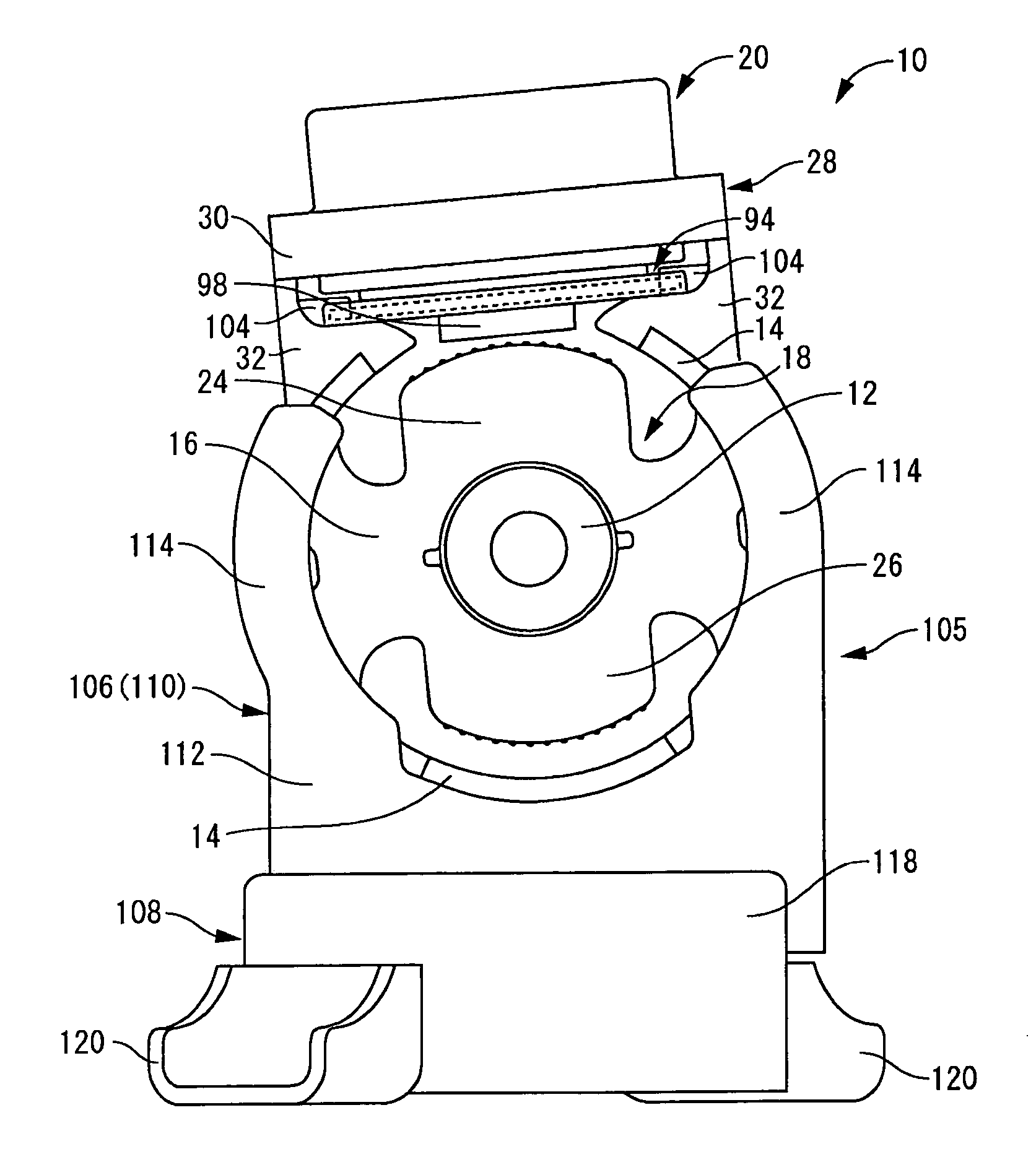
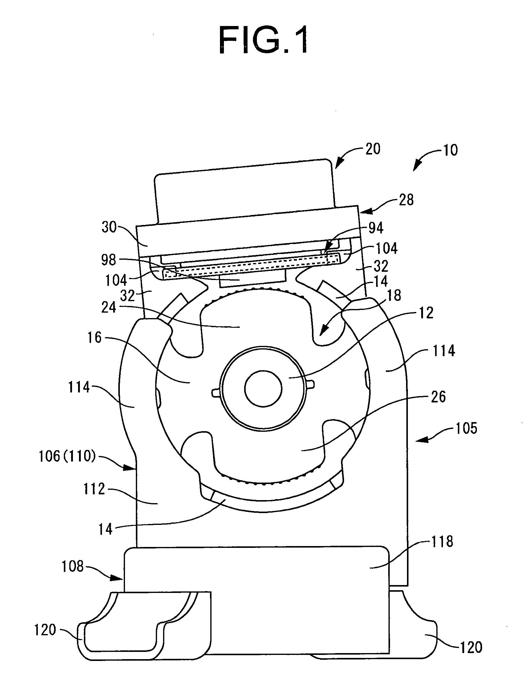
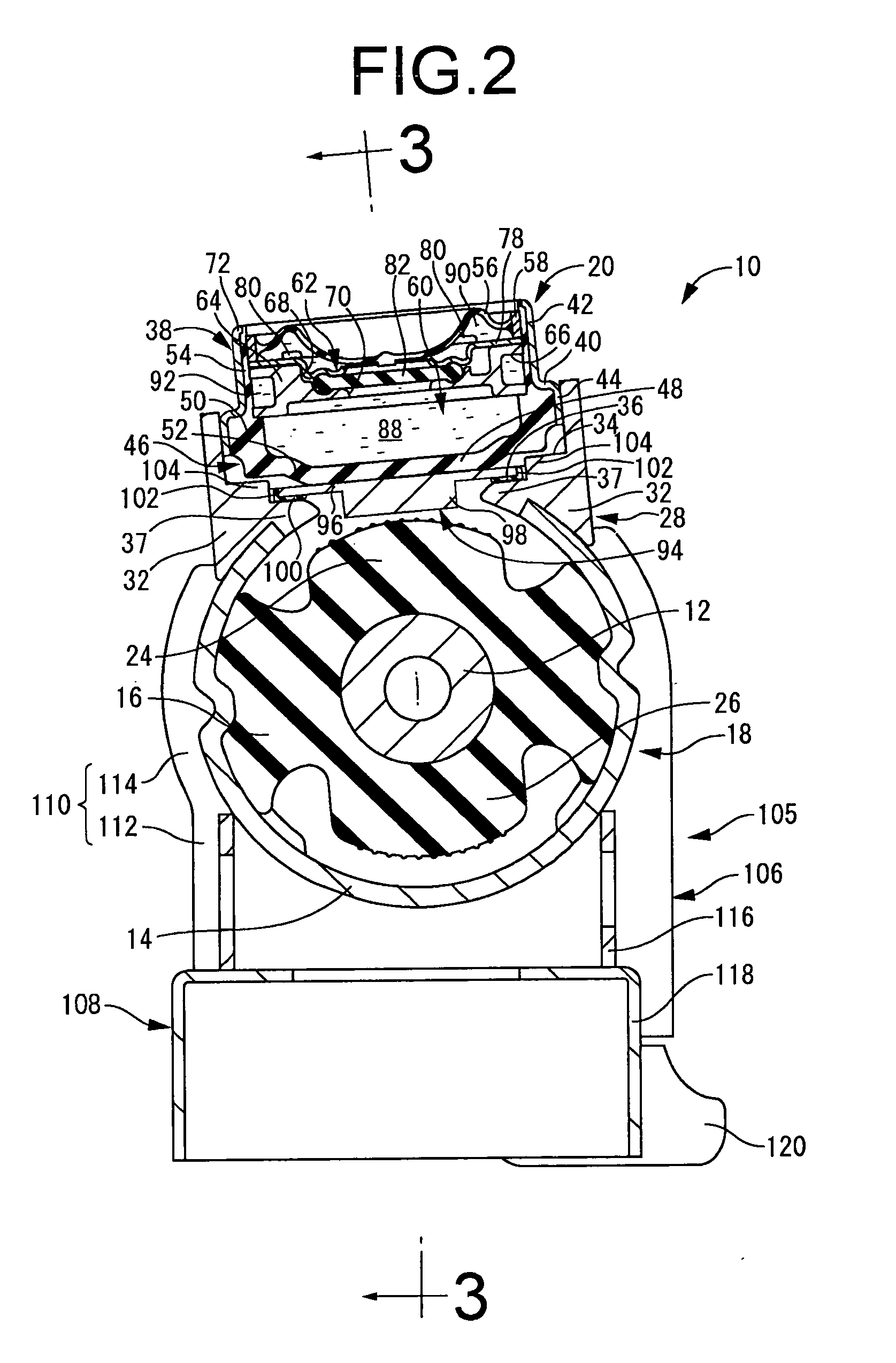
[0038]Referring first to FIGS. 1 to 3, there is depicted an automotive engine mount 10 as the vibration damping device according to the invention. The engine mount 10 includes a main mount unit 18 having an inner shaft member 12 of metal as the first mounting member, an outer tubular member 14 of metal as the second mounting member (outer tubular member) connected to one another by a main rubber elastic body 16, and as the fluid-filled unit, a fluid-filled cassette 20 for attachment to the main mount unit 18. The inner shaft member 12 is mounted on the power unit (not shown) constituting one component of a vibration transmission system, while the outer tubular member 14 is mounted on the vehicle body (not shown) constituting the other component of the vibration transmission system, to install the engine mount 10 between the power unit and the vehicle body and thereby providing vibration damped support of the power unit on the vehicle body. In the following description, the vertical ...

second embodiment

[0110]Furthermore, whereas in the preceding second embodiment the projecting distal edge of the contacting projection 126 is a flat surface of annular shape parallel to the upper face of the plate portion 96, it may instead have an arcuate curving contour that is upwardly convex. In this case it will be possible to advantageously avoid damage to the rubber elastic wall 46 in the section thereof contacted by the contacting projection 126, and to ensure durability of the rubber elastic wall 46 as a result.

[0111]In the first and second embodiments, the cutout portion 22 is formed in a portion of the perimeter of the outer tubular member 14, and the fluid-filled cassette 20 is attached to the outer tubular member 14 at the location where the cutout portion 22 has been formed. However, it would be possible to instead form multiple cutout portions 22 at the perimeter of the outer tubular member 14 and to attach fluid-filled cassettes 20 at each of the locations where these cutout portion ...


PUM


Abstract

A vibration damping device including: a main rubber elastic body connecting a first and a second mounting members; a fluid-filled unit having a tubular housing closed off by a rubber elastic wall and a flexible film for providing therein a fluid chamber filled with a non-compressible fluid, and a partition member positioned within the fluid chamber to form on a first side thereof a primary fluid chamber partly defined by the rubber elastic wall, and on the other side thereof a secondary fluid chamber partially defined by the flexible film, with these chambers communicating through an orifice passage; and a rigid piston member. Upon input of vibration across the first and second mounting members, pressure fluctuations is exerted on the primary fluid chamber through elastic deformation of the rubber elastic wall of the fluid-filled unit induced through pushing by the contacting member via the piston member.

Description

INCORPORATED BY REFERENCE[0001]The disclosure of Japanese Patent Application No. 2007-246189 filed on Sep. 21, 2007 including the specification, drawings and abstract is incorporated herein by reference in its entirety.BACKGROUND OF THE INVENTION[0002]1. Field of the Invention[0003]The present invention relates in general to a vibration damping device adapted for use as an engine mount in an automobile for example, and more particularly to a vibration damping device of fluid filled type that utilizes vibration damping action produced on the basis of flow action of a fluid that fills the interior.[0004]2. Description of the Related Art[0005]In the past there have been proposed vibration damping devices having a structure in which a first mounting member that is mounted on one component of a vibration transmission system is positioned spaced apart in relation to a second mounting member that is mounted on the other component of the vibration transmission system, with the first mountin...

Claims


Application Information

Patent Timeline
IPC IPC(8): F16F15/023
CPCF16F13/14
Inventor YOSHII, NORIAKIKAWAI, MOTOHIRO
Owner TOKAI RUBBER IND LTD
Learn More