Forging die apparatus

a technology of forging dies and dies, which is applied in forging presses, forging/pressing/hammering apparatuses, forging/hammering/pressing machines, etc., can solve the problems of centering deviation, inconvenience, and inconvenientness, and achieve the effect of high accuracy of coaxial degree of forged products

Inactive Publication Date: 2006-05-16
HONDA MOTOR CO LTD
View PDF7 Cites 17 Cited by
  • Summary
  • Abstract
  • Description
  • Claims
  • Application Information

AI Technical Summary

Benefits of technology

[0028]A general object of the present invention is to provide a forging die apparatus which makes it possible to maintain a highly accurate coaxial degree of a forged product obtained by forging.
[0029]A principal object of the present invention is to provide a forging die apparatus which makes it possible to suppress occurrence of scuffing between a punch and a die.
[0030]Another object of the present invention is to provide a forging die apparatus which makes it possible to assemble an upper die and a lower die in an integrated manner so that the coaxial degree is maintained highly accurately between the upper die and the lower die.

Problems solved by technology

In this case, if the clearance A is small, the following inconvenience arises.
For example, when an outer cup for constructing a constant velocity universal joint is formed by forging, an inconvenience arises in that the axis of a cup of the outer cup is not coincident with the axis of a shaft thereof, i.e., the centering deviation occurs.
As a result, an inconvenience arises in that any dispersion occurs in the dimension of an obtained forged product in the thickness direction.
Therefore, the conventional technique involves an inconvenience that cutting processing should be applied after the forging in order to obtain a constant bottom thickness dimension of the cup of the outer cup.
If the forming load, which is applied to the material, hugely exceeds a preset value due to the influence of the elongation (if a overloaded forming load is applied), the mechanical press 31 is stopped in a locked state, resulting in an inconvenience that it is impossible to perform continuous forming.
Therefore, even if a projection (not shown) for forming the centering hole is provided at one end of the knockout pin 48 for constructing the die apparatus concerning the conventional technique, an inconvenience arises in that it is impossible to correctly form the centering hole at the center of one end of the shaft of the outer cup formed by the forging.
As a result, the die apparatus concerning the conventional technique involves the following inconvenience.
On the other hand, if the clearance C is made narrow, another inconvenience arises in that it is difficult to perform forward and backward movement of the knockout pin 48 due to the action of sliding friction with respect to the hole 42.

Method used


Image

  • Forging die apparatus
  • Forging die apparatus
  • Forging die apparatus

Examples


first embodiment

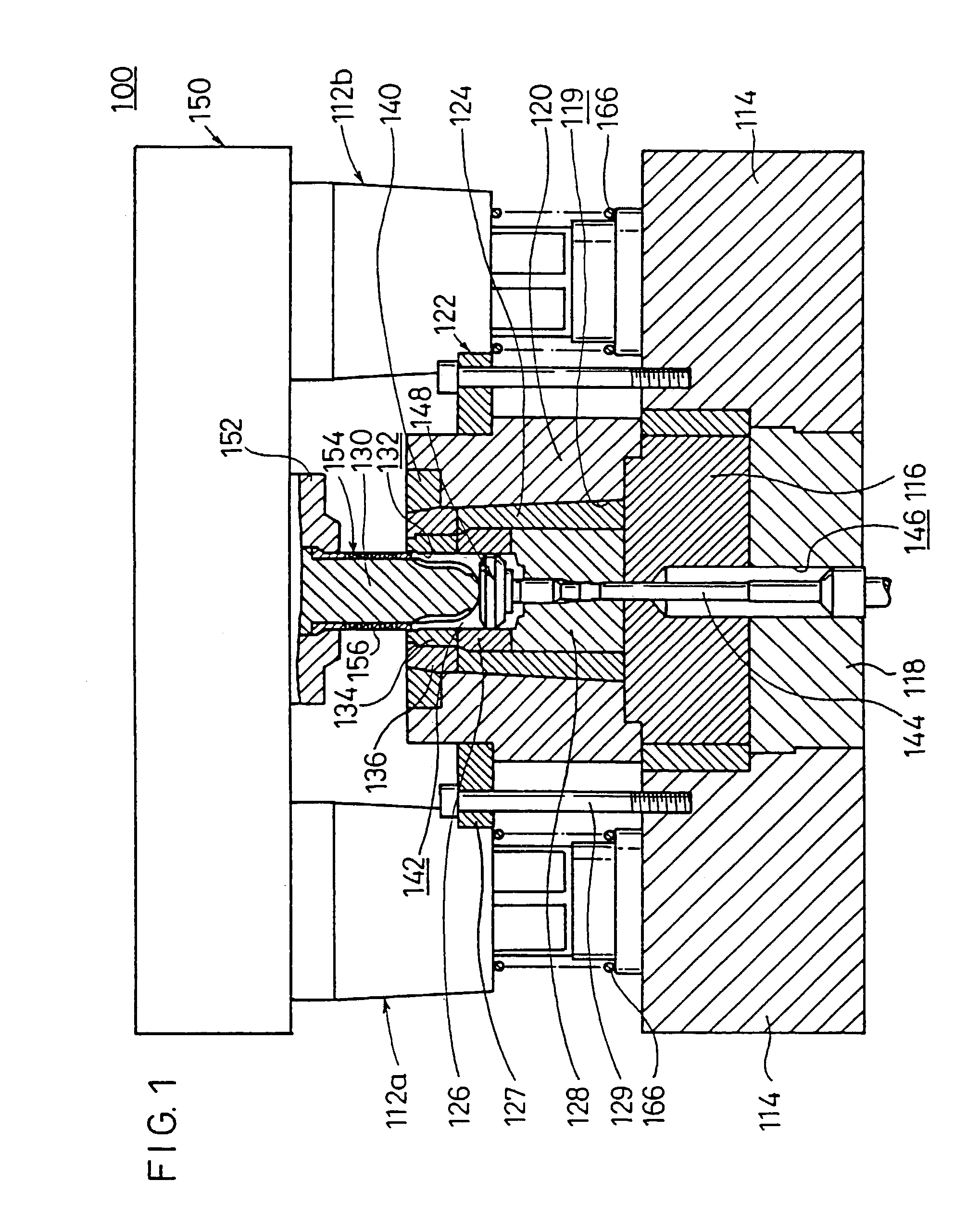
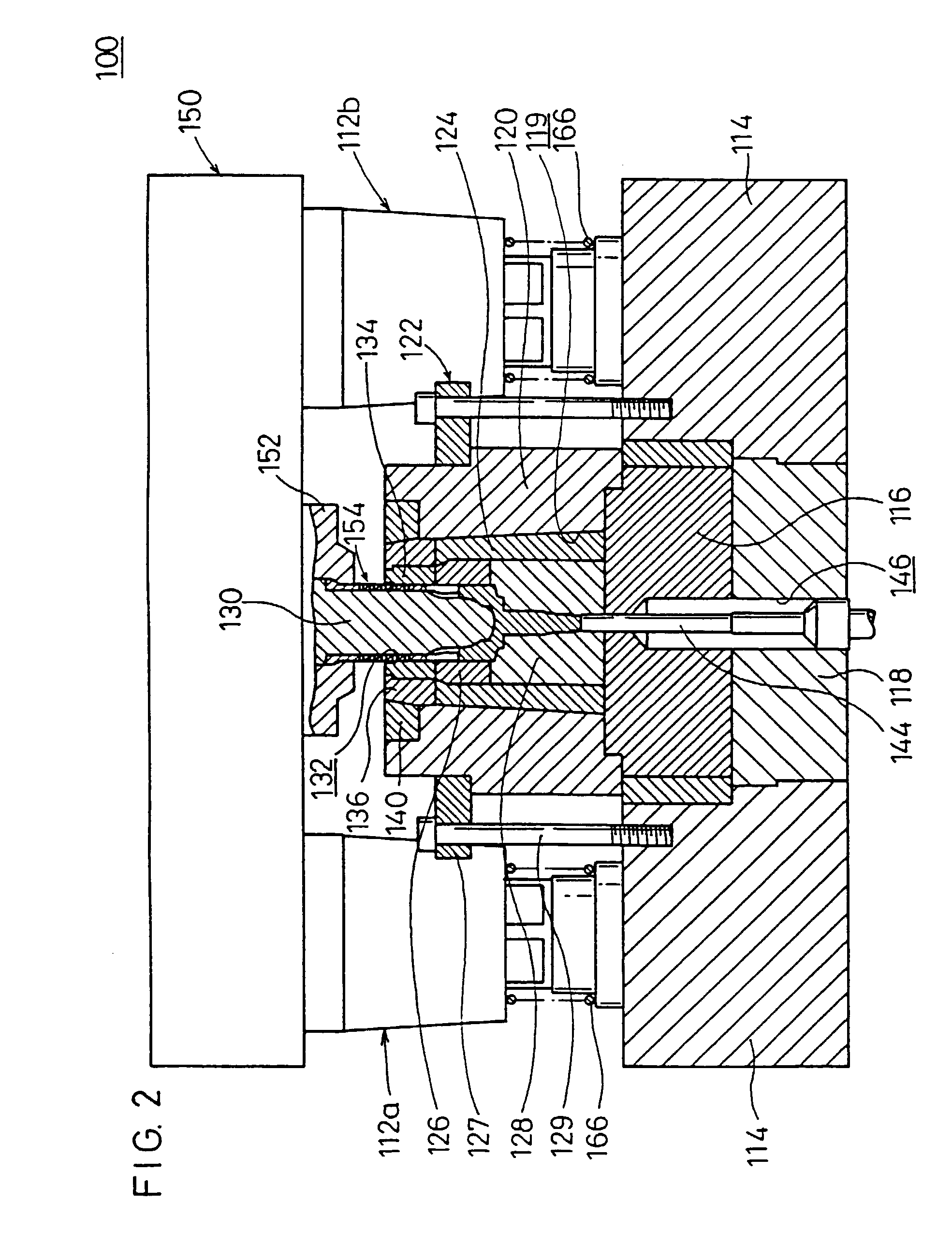
[0082]With reference to FIG. 1, reference numeral 100 indicates a forging die apparatus according to the present invention. The forging die apparatus 100 comprises a first die holder 114 on which a plurality of guide means 112a to 112d (see FIG. 4) are vertically provided in the close vicinity of four corners, and second and third die holders 116, 118 which are provided and stacked at the center of the first die holder 114.

[0083]A thick-walled forcible insertion ring 120, which is formed in an integrated manner, is fixed on the second die holder 116 by the aid of a clamping means 122. An upper die 126 and a lower die 128 are integrally joined in a hole 119 of the forcible insertion ring 120 via a sleeve 124 which is formed to have a thin-walled cylindrical configuration.

[0084]As shown in FIG. 3, the hole 119 of the forcible insertion ring 120 is formed to have a tapered configuration in which the diameter is gradually reduced from its lower portion to its upper portion in an assembl...

second embodiment

[0137]The forging die apparatus 200 according to the present invention is basically constructed as described above. Next, its operation, function, and effect will be explained.

[0138]As a preparatory operation, the cooling medium supply source (not shown) is energized beforehand to previously supply the cooling medium via the unillustrated tube to the communication passage 257 formed between the cylindrical member 154 and the main punch body 230.

[0139]The secondary formed product 148 (see FIG. 12) as the forging material is charged in the cavity 142 in a state in which the main punch body 230 is arranged at an unillustrated lifted position. The main punch body 230 is lowered integrally with the elevating member 150 connected to the ram 36 in accordance with the driving action of the mechanical press 31 to give the state shown in FIG. 20. Thus, the forging is started.

[0140]When the main punch body 230 is lowered integrally with the elevating member 150, any unbalanced load in the late...

third embodiment

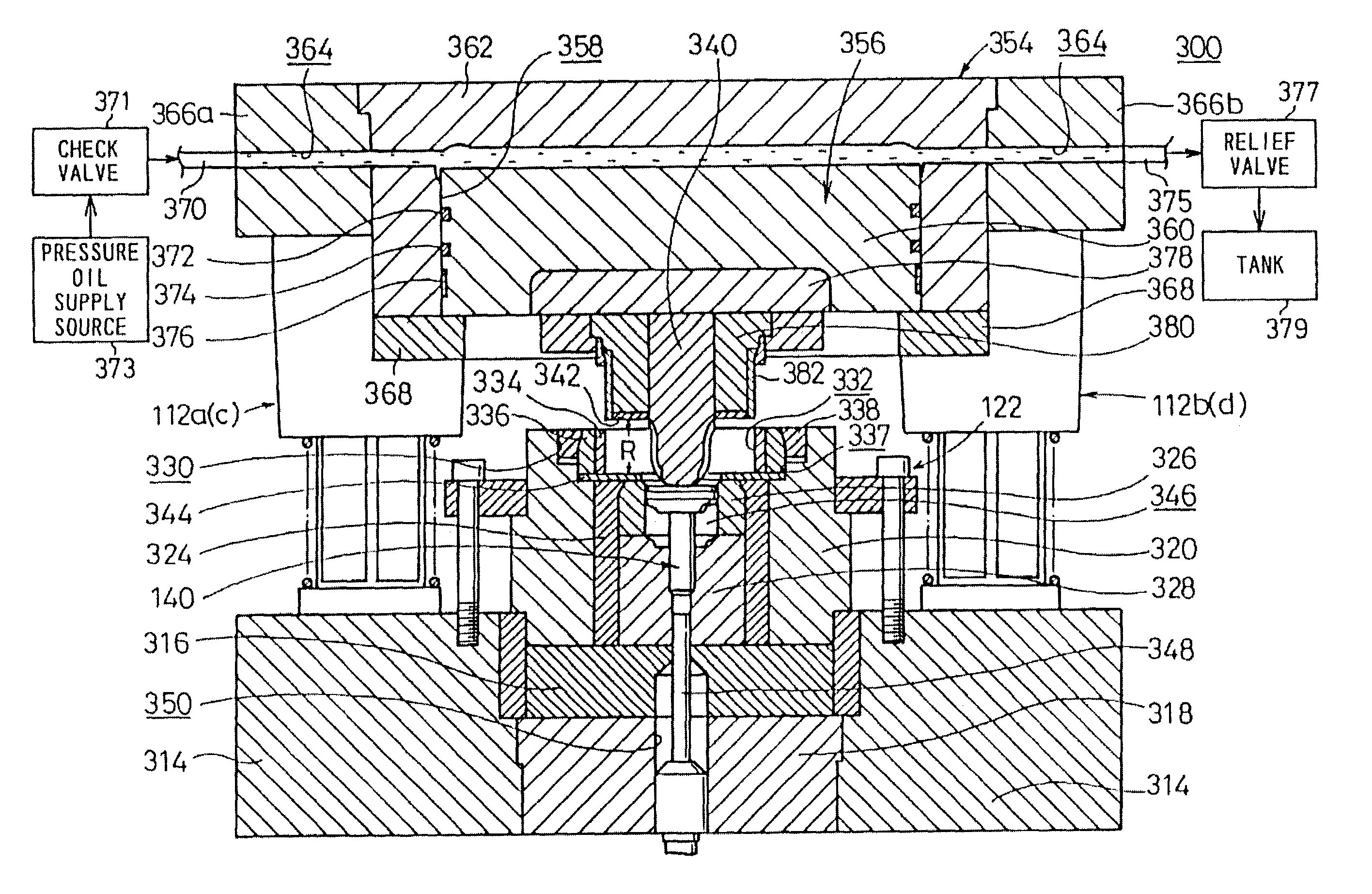
[0162]Next, a forging die apparatus 300 according to the present invention is shown in FIG. 28.

[0163]The forging die apparatus 300 comprises a first die holder 314 on which a plurality of guide means 112a to 112d (see FIG. 4) are vertically provided in the close vicinity of four corners, and second and third die holders 316, 318 which are provided and stacked at the center of the first die holder 314.

[0164]A thick-walled forcible insertion ring 320, which is formed in an integrated manner, is fixed on the second die holder 316 by the aid of a clamping means 122. An upper die 326 and a lower die 328 are integrally joined in a hole of the forcible insertion ring 320 via a sleeve 324 which is formed to be thin-walled.

[0165]A first ring member 334 formed with a hole 332, a second ring member 336 externally fitted to the first ring member 334, and a clamping ring 338 for holding the first ring member 334 and the second ring member 336 are provided in an annular recess 330 formed at an up...


PUM

PropertyMeasurementUnit
temperatureaaaaaaaaaa
rotary driving forceaaaaaaaaaa

Abstract

A forging die apparatus comprises a punch for applying a pressurizing force to a forging material arranged in a cavity, a cylindrical member installed to surround a part of outer circumference of the punch, for making displacement integrally with the punch, and a first ring member formed with a hole for forcibly inserting the cylindrical member therein when the punch applied the pressurizing force to the forging material.

Description

CROSS REFERENCE TO RELATED APPLICATIONS[0001]This application is a continuation-in-part of applicatiton Ser. No. 09 / 487,880, filed on Jan. 20, 2000, now abandoned, which in turn is a divisional application of application Ser. No. 09 / 177,364, filed on Oct. 23, 1998, now U.S. Pat. No. 6,035,688. The entire contents of each of the above-identified applications are hereby incorporated by reference and priority is claimed under 35 U.S.C. § 120.BACKGROUND OF THE INVENTION[0002]1. Field of the Invention[0003]The present invention relates to a forging die apparatus for processing a forging material arranged in a cavity formed by a die member so that the forging material is subjected to forging in accordance with a pressurizing action of a punch.[0004]2. Description of the Related Art[0005]A die apparatus has been hitherto known, in which a forging material is inserted into a cavity formed by an upper die and a lower die which are joined to one another, and a pressurizing force is applied to...

Claims


Application Information

Patent Timeline
Patent Type & Authority Patents(United States)
IPC IPC(8): B21J13/02B21J5/02B21J13/14B21K1/76
CPCB21J5/02B21J13/02B21K1/765B21K1/762B21J13/14
Inventor NAGAO, YUICHIDOI, YOSHIHISAOHAMA, TSUKASHI
Owner HONDA MOTOR CO LTD
Why Eureka
Try Eureka