Large target surface high-precision optics heat-free temperature measurement lens and adjustment method

A high-precision, large-target technology, used in optical radiometry, radiation pyrometry, optics, etc., can solve the problem that the imaging field angle is small and cannot fully obtain the overall structure, concentricity, accuracy and axial position of the test object. Accuracy, optical system focal length change and other issues, to achieve the effect of reasonable lens design, wide-spectrum confocal, and clear imaging

Inactive Publication Date: 2017-02-15
FUJIAN FUGUANG TIANTONG OPTICS
View PDF6 Cites 2 Cited by
  • Summary
  • Abstract
  • Description
  • Claims
  • Application Information

AI Technical Summary

Problems solved by technology

Because infrared optical materials and mechanical materials will produce thermal deformation when the temperature changes, the drastic change of working temperature will cause the focal length change of the optical system, the image surface is elegant, and the image quality is reduced.
In order to eliminate or reduce the impact of temperature changes on the imaging of the optical system, corresponding compensation techniques must be used to keep the focal length of the optical system unchanged within a large temperature range to ensure good imaging quality. In addition, existing lenses have imaging The small field of view cannot completely obtain the overall structure of the test object. In addition, the inaccuracy of concentricity, precision and axial position also affects the implementation of compensation technology

Method used


Image

  • Large target surface high-precision optics heat-free temperature measurement lens and adjustment method
  • Large target surface high-precision optics heat-free temperature measurement lens and adjustment method
  • Large target surface high-precision optics heat-free temperature measurement lens and adjustment method

Examples


Embodiment Construction

[0023] In order to make the above-mentioned features and advantages of the present invention more comprehensible, the following specific embodiments are described in detail with reference to the accompanying drawings.

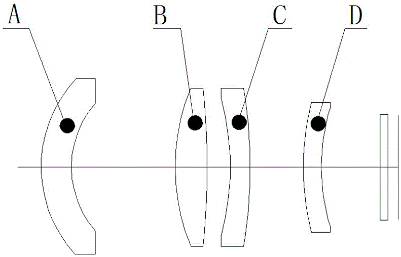
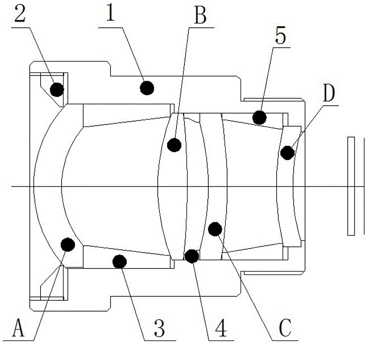
[0024] Such as Figure 1~2 As shown, a high-precision optical athermalization temperature measurement lens with a large target surface includes a negative crescent lens A, a biconvex lens B, a negative crescent lens C, and a negative crescent lens D arranged in sequence along the incident direction of light from left to right.

[0025] In the embodiment of the present invention, the air gap between the negative crescent lens A and the biconvex lens B is 13mm, the air gap between the biconvex lens B and the negative crescent lens C is 3mm, and the negative crescent lens C and the The air space between the negative crescent lenses D is 7mm.

[0026] In the embodiment of the present invention, the material of the negative crescent lens A, biconvex lens B, negativ...


PUM


Abstract

The invention relates to a large target surface high-precision optics heat-free temperature measurement lens which comprises a crescent lens A, a lenticular lens B, a crescent lens C and a crescent lens D, wherein the crescent lens A, the lenticular lens B, the crescent lens C and the crescent lens D are arranged in order along the left-right incident direction of light. The invention further relates to a large target surface high-precision optics heat-free temperature measurement lens adjustment method. According to the invention, the temperature measurement lens has the advantages of large relative aperture, large field angle, low distortion, large target surface, self-adaptive optics heat-free compensation, light structure and the like; different refractive index changes of an optical material at different temperatures are used to compensate the influence of temperature change on a focal plane; a heat-free design structure is simpler; the structure of the whole product is smaller; the weight is lighter; stable optical axis imaging is more clear; the reliability is higher; the requirement of the product imaging performance of a user is met; and the structure is more convenient for a customer to use.

Description

technical field [0001] The invention relates to a high-precision optical athermalization temperature measuring lens with a large target surface and an adjustment method. Background technique [0002] As a non-contact temperature measurement technology, infrared temperature measurement technology has many advantages compared with traditional temperature measurement technology. First, its measurement does not interfere with the temperature measurement field, does not affect the temperature distribution, and has high accuracy and precision; secondly, Infrared temperature measurement is fast and can be observed in real time, which has great advantages in measurement; thirdly, infrared temperature measurement can be near or far, and can work at night, with strong adaptability; finally, infrared temperature measurement has a wide range and theoretically has no upper limit for testing. This makes infrared temperature measurement technology widely used in power industry, aerospace, ...

Claims


Application Information

Patent Timeline
Patent Type & Authority Applications(China)
IPC IPC(8): G02B7/02G02B13/00G02B13/06G02B13/14G01J5/08G01J5/02
CPCG02B7/021G02B7/028G02B13/008G02B13/06G02B13/14G01J5/0806G01J2005/0077G01J5/068
Inventor 刘涛何武强仇力陈丽娜张华
Owner FUJIAN FUGUANG TIANTONG OPTICS
Why Eureka
Try Eureka