
Highly efficient heat exchanger and combustion chamber assembly for boilers and heated air generators

a heat exchanger and combustion chamber technology, applied in the direction of air heaters, fluid heaters, tubular elements, etc., to achieve the effect of small exchange size, high thermal load, and no negative load loss through the system

Inactive Publication Date: 2006-05-16
RIGAMONTI ANGELO
View PDF9 Cites 12 Cited by
  • Summary
  • Abstract
  • Description
  • Claims
  • Application Information

AI Technical Summary

Benefits of technology

[0008]Within the scope of the above mentioned aim, a main object of the present invention is to provide such a heat exchanger, of the tube sheet and combustion chamber type, allowing to fit high thermal loads, with a comparatively small exchange size, and allowing, moreover, to hold a turbulent motion of the combustion fumes, without generating negative load losses through the system.

Problems solved by technology

A further problem is that of the high heating of the combustion chamber, operating in cooperation with premixed gas burners having a very high unit power for flame surface.

Method used


Image

  • Highly efficient heat exchanger and combustion chamber assembly for boilers and heated air generators
  • Highly efficient heat exchanger and combustion chamber assembly for boilers and heated air generators
  • Highly efficient heat exchanger and combustion chamber assembly for boilers and heated air generators

Examples


Embodiment Construction

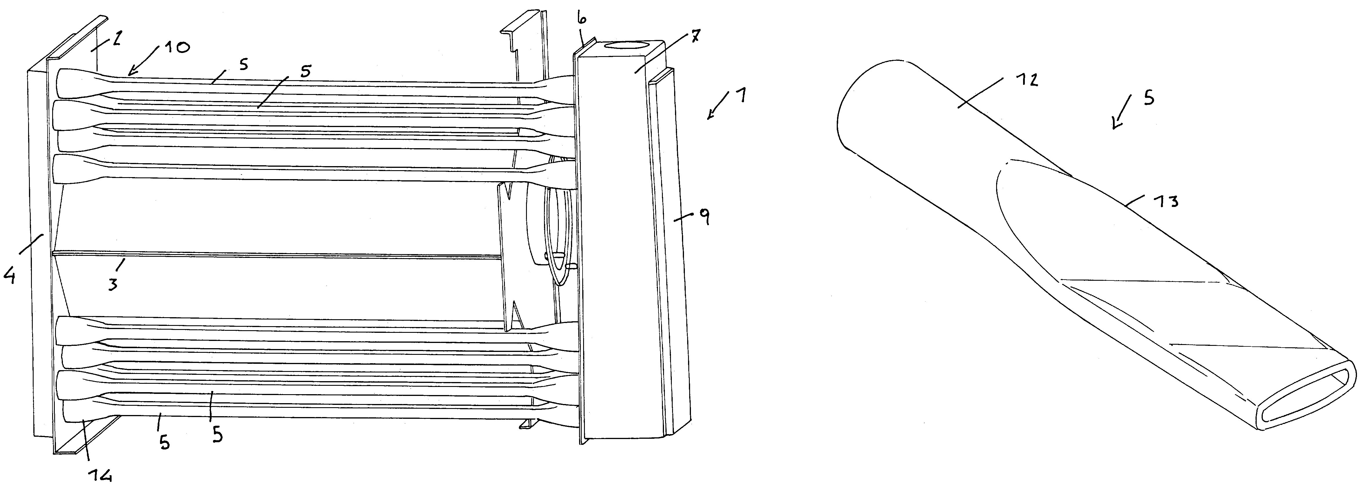
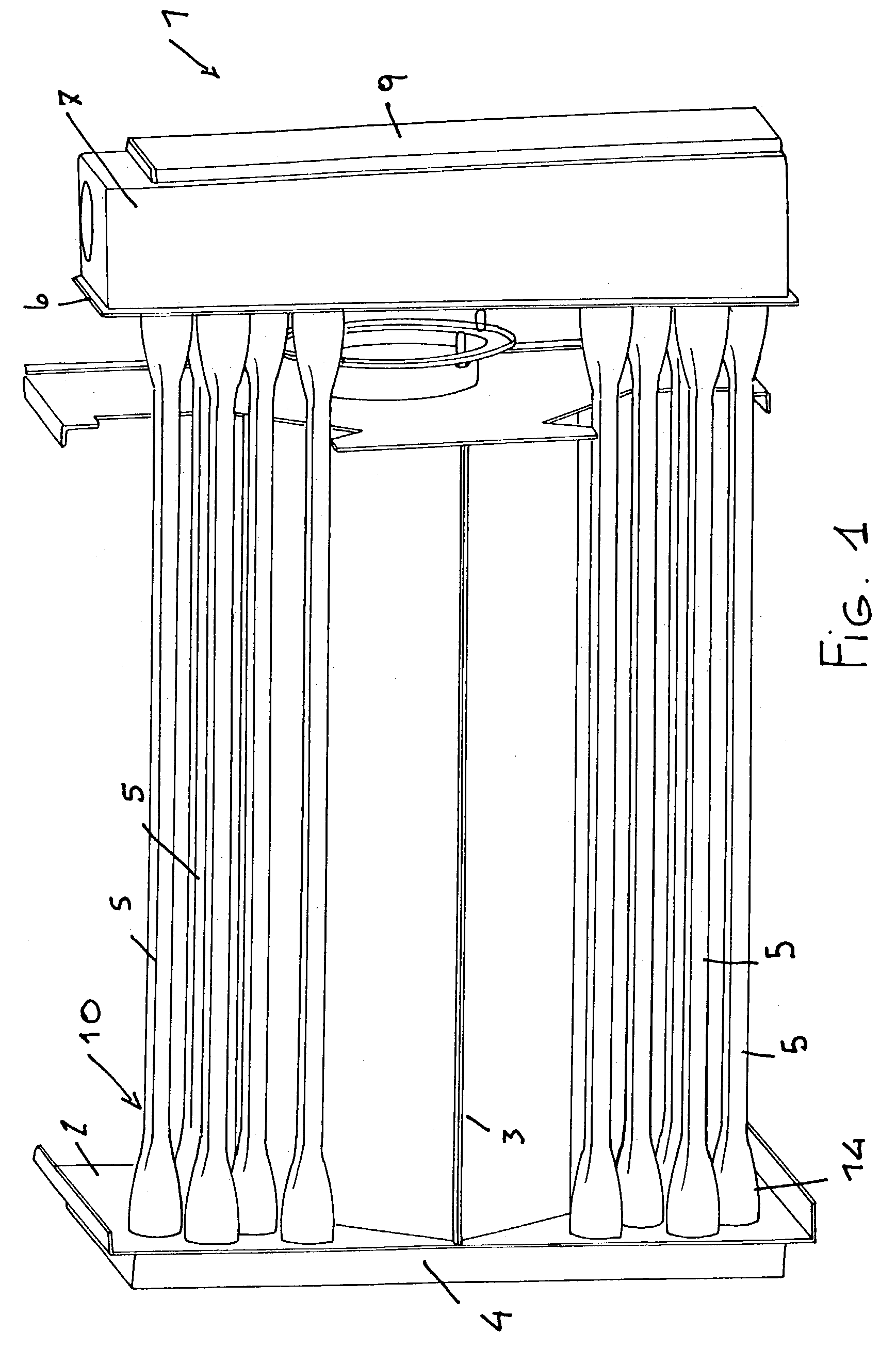
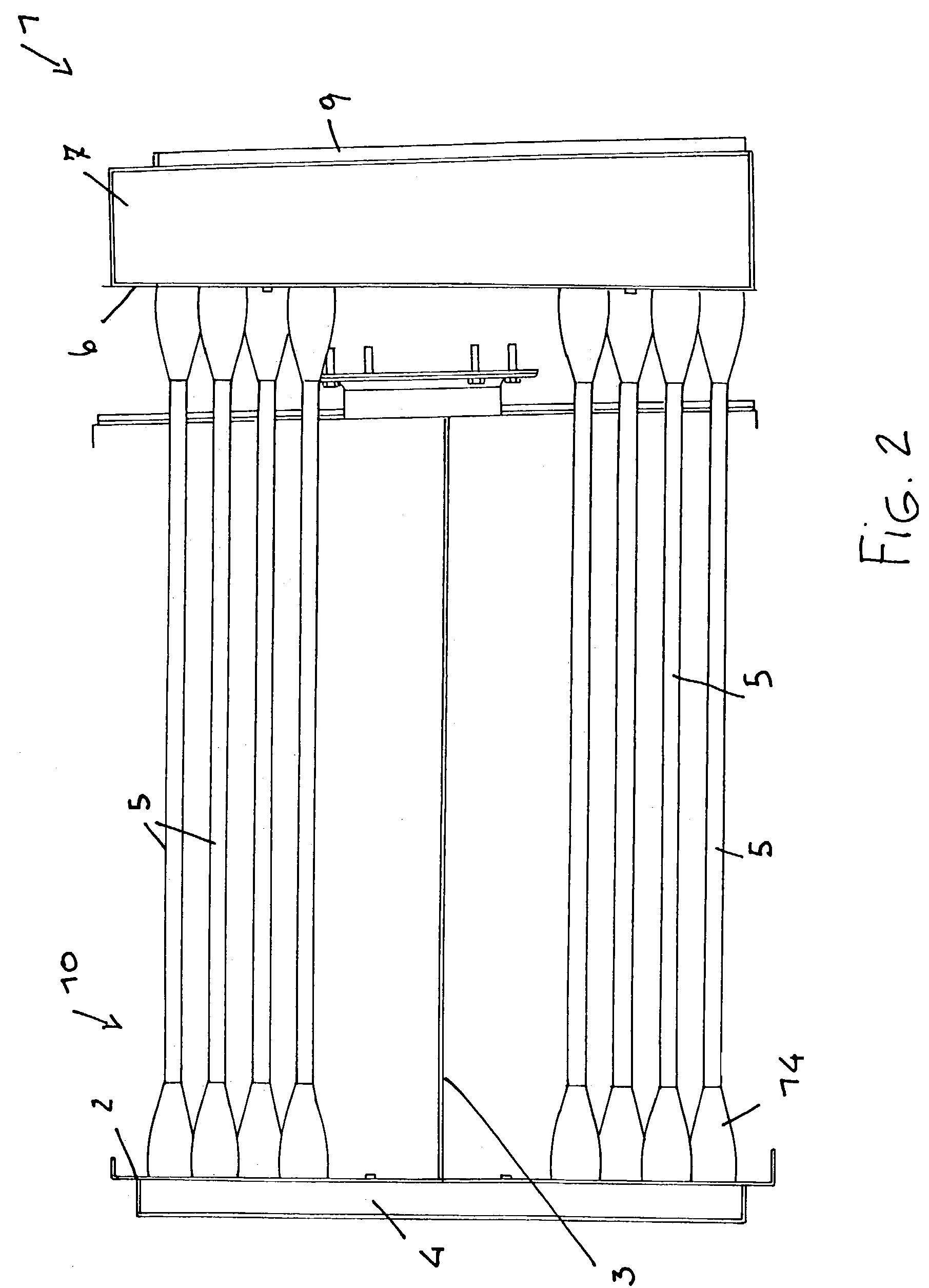
[0016]With reference to the number references of the above mentioned figures, the assembly according to the present invention, which has been generally indicated by the reference number 1, comprises a combustion chamber 3, associated with a heat exchanger, generally indicated by the reference number 10, which essentially comprises a plurality of heat exchanger tubes 5, the ends of which are coupled to a rear tube plate or sheet 2 and a front tube plate or sheet 6.

[0017]The rear tube plate 2, in particular, is coupled to a rear manifold 4.

[0018]According to a main feature of the present invention, each tube 5 has, starting from the front plate 6 to the rear plate 2, a gradually tapering or reducing cross-section.

[0019]More specifically, the tubes 5 have a front attachment portion 12 (FIG. 4) having a circular cross-section and comprising a portion or length 13 where the cross-section is narrowed to an elliptical configuration.

[0020]On this section a deforming operation is carried out...


PUM


Abstract

The present invention relates to a heat exchanger and condensation combustion chamber assembly, comprising a plurality of tubes and including a front plate and a rear plate connected to the combustion chamber with a drop pattern.Each of the heat exchanger tubes comprises a variable area cross section, with a flat portion at a middle region, to provide a larger thermal exchange surface.The middle region is subjected to a crossed cut molding process to provide a helical type of fume path, suitable to enhance the efficiency of the assembly, owing to an increased thermal exchange between the fumes and heated air flows.The combustion chamber having a cross section of drop shape allows to properly solve the problem related to the very high temperatures generated by recent cylindrical gas burners having a metal mesh surface generating great amounts of heat, which must be disposed of in a thermal exchange process with the heated air flow.

Description

BACKGROUND OF THE INVENTION[0001]The present invention relates to a heat exchanger and a condensation combustion chamber assembly for the passage of the fumes generated by air / gas combustion, produced by a pre-mixed burners coupled to the combustion chamber.[0002]Such an assembly, as is known, has a very high efficiency, of the order of 105% and generates, as combustion products, in addition to the combustion fumes, also water steam, which is conveyed to the outside environment, through a dedicated conveying duct.[0003]In such an embodiment, it is necessary to increase or enhance the thermal exchange between the fumes and secondary air to be heated, while preventing any generations of laminar flows with thermal gradients inside the exchanging tube, which would cause a decrease of the thermal exchange with the secondary fluid.[0004]A further problem is that of the high heating of the combustion chamber, operating in cooperation with premixed gas burners having a very high unit power ...

Claims


Application Information

Patent Timeline
IPC IPC(8): F24H3/08F28F1/02F28F13/08
CPCF24H3/087F28F13/08F28F1/025F28F13/12
Inventor RIGAMONTI
Owner RIGAMONTI ANGELO
Learn More