
Tray

Active Publication Date: 2006-05-16
KNOLL PRINTING & PACKAGING
View PDF13 Cites 29 Cited by
  • Summary
  • Abstract
  • Description
  • Claims
  • Application Information

AI Technical Summary

Benefits of technology

[0009]A tray so arranged is less expensive and stronger than prior art trays. The tray is of high quality and is appropriate for expensive goods. The cover is not glued to the insert, which reduces manufacturing costs and avoids the problem whereby the insert is known to be seen through the cover. The inside of the tray of the invention is completely covered by the cover and floor whereby no raw cardboard of the insert is visible, which provides a more appealing tray decoration. Due to the assembly method of the tray the cover can be of a heavy paper or light cardboard, as opposed to a light paper cover, which is advantageous for all forms of decorating. Furthermore the light cardboard is advantageous for creasing, which provides advantages in assembly of the tray. Since an entire surface of the cover is not required to be bonded to the insert, all forms of decorative methods can be utilised such as decoration, deep raised embossing, hot leaf stamping, imprinting, films, foils and mylars, and other coatings. Essentially, there is no interaction between the insert and the cover affecting the decoration of the cover.
[0011]The cover is preferably of card and may be in the thickness range 0.1–0.25 mm. More preferably the cover has a thickness in the range 0.2–0.25 mm. This cover thickness is greater than prior art trays utilising an insert and a cover and is made possible by the manner in which the tray is constructed. The card permits creasing operations to be performed which thereby reduces cracking of the cover on folding. The card is capable of accepting all forms of decorating in a much preferable manner to the paper of the prior art tray with an insert.
[0015]Opposite flaps may be provided with secondary tabs on the outer portion thereof which may be bonded to adjacent flaps. This provides additional strength to the assembled tray. In the preferred embodiment these secondary tabs are provided on the outer portions of the flaps.
[0018]In yet a further alternative embodiment the cover is bonded to the insert at spaced locations to provide a decorative effect to the cover and which enhances the appearance, such as a quilted appearance.
[0031]The method may further comprise the step of providing opposite flaps with secondary tabs and adhesively bonding the secondary tabs to the adjacent flaps. Secondary tabs so arranged and bonded to adjacent flaps advantageously provide the assembled tray with additional strength.

Problems solved by technology

The medium weight card can be decorated, but the tray assembled therefrom is typically not as strong as the tray having an adhesively attached paper cover.
Some disadvantages are associated with the prior trays.
Raw card is often exposed on the inside of the trays which is a drawback when the tray is used for presenting expensive or luxury items.
The raw card may be covered by a separate lightweight cover for decoration purposes which is glued flat to the inside of the tray but this increases the manufacturing costs and may provide a non uniform appearance to the inside of the tray.
In the case of the tray with a paper cover, the requirement for an entire surface of the cover to be bonded to the card increases manufacturing costs.
In the case of the paper cover the requirement for complete bonding imposes limitations on the material and decorating methods.
Often the cover material is embossed prior to bonding, but the adhesive used tends to reduce the embossing effect, which is undesirable.
A heavier cover material can be used to improve the creasability but this often results in a puffy appearance of a finished tray.

Method used


Image

  • Tray
  • Tray

Examples


Embodiment Construction

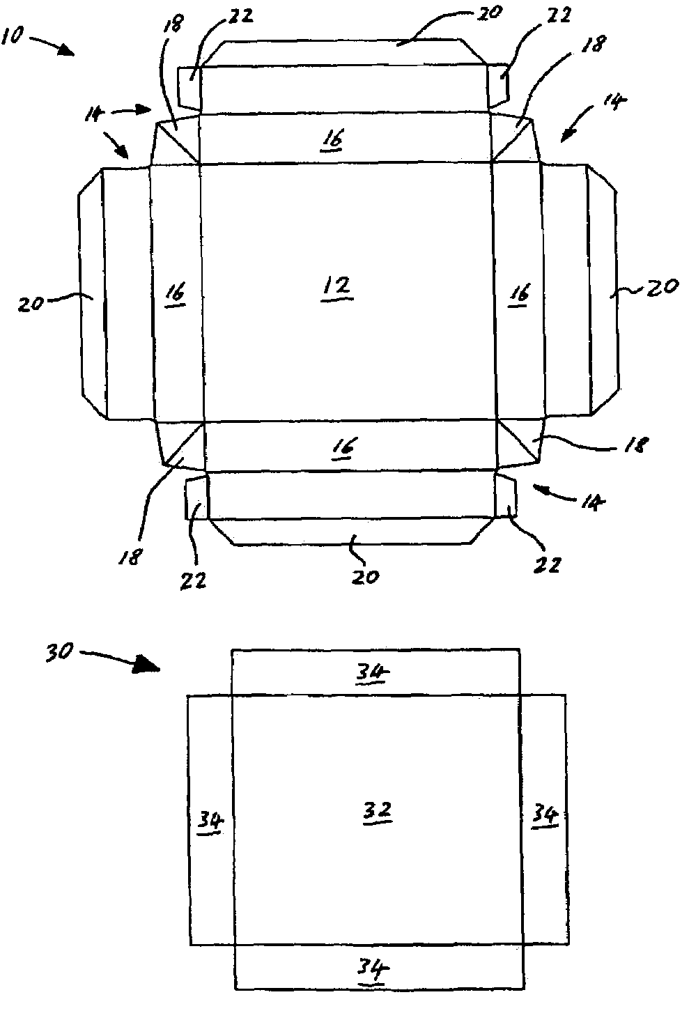
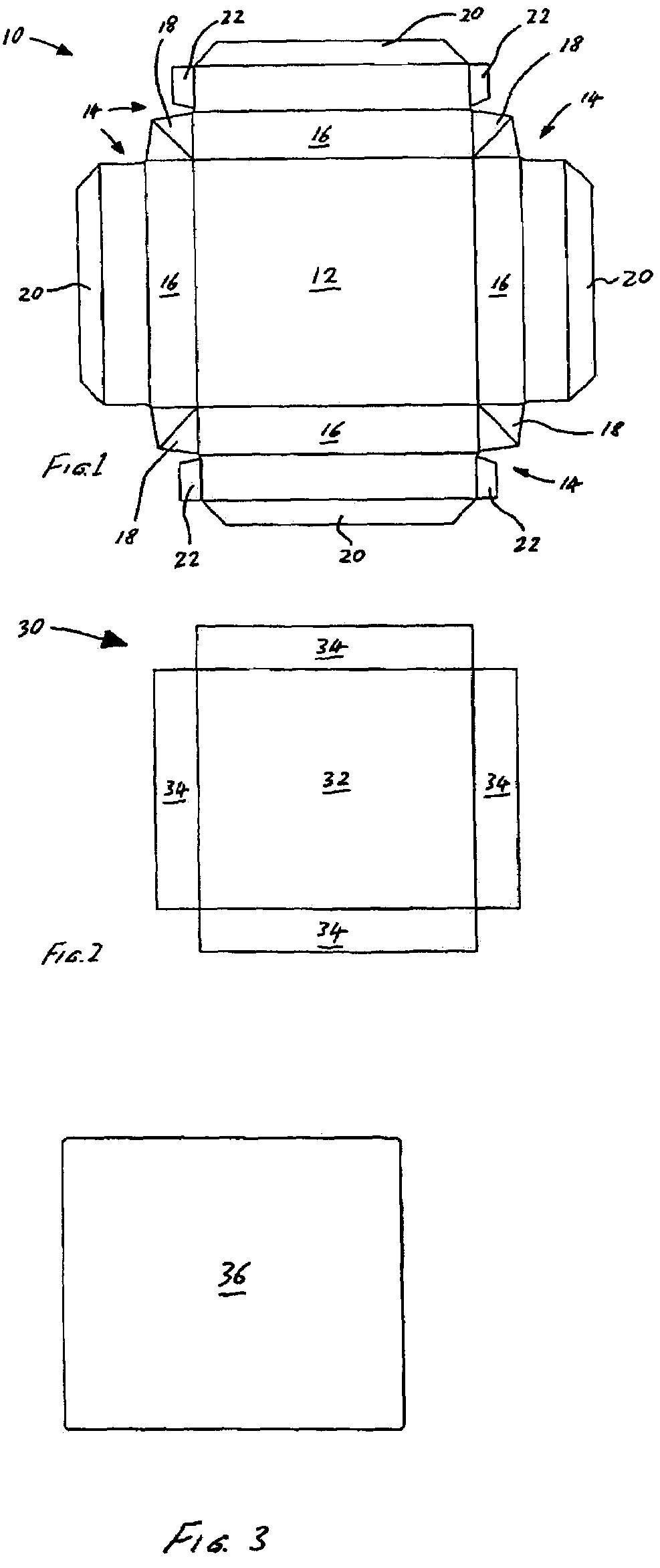
[0036]Referring firstly to FIG. 1 there is shown an unfolded (planar) cover blank for a tray according to the present invention, generally designated 10. The cover 10 comprises a rectangular panel 12 with a flap 14 appended to each side of the panel 12. A portion 16 of each flap 14 is connected to an adjacent flap 14 with a gusset 18. Each flap 14 has a tab 20 appended thereto. Two opposing flaps 14 are further provided with secondary tabs 22. The cover 10 is of light card which is typically in the thickness range 0.1–0.25 mm.

[0037]FIG. 2 is a plan view of an unfolded insert blank for the tray manufactured with the blank of FIG. 1, generally designated 30. The insert 30 comprises a rectangular base 32 which is substantially the same size as the panel 12. The base 32 has a wall 34 appended to each side. The insert 30 is of heavy cardboard and is typically in the range 0.5–3 mm. The walls 34 are intended to be folded-up at right angles, and are of the same height.

[0038]FIG. 3 is a pla...


PUM


Abstract

The invention relates to a cover, an insert and a floor, and a method for manufacturing a tray therefrom. The cover comprises a planar rectangular panel with a flap on each edge, a portion of each flap being connected to an adjacent flap with a gusset, each flap having a tab at the free edge thereof, wherein the floor comprising a planar rectangle which is substantially the same size as the panel, and wherein the insert comprising a planar rectangular base which is substantially the same size as the panel, the base having a wall portion on each edge, each flap being substantially twice the size of each wall portion, wherein in use the base is aligned with the panel, the wall portions are upright, the flaps extend around the respective wall portions and the tabs are folded onto the base, the floor being aligned with the base and the panel, and being bonded to the tabs. A tray so arranged is less expensive and stronger than prior art trays. The cover is not glued to the insert, which reduces manufacturing costs and provides greater versatility in decoration options for the cover.

Description

TECHNICAL FIELD[0001]The present invention relates to a tray or open box, and in particular, to a cover blank and a tray blank and a method for manufacturing a tray therefrom.BACKGROUND TO THE INVENTION[0002]It is known to combine a cover blank of paper and a tray blank of heavy card to manufacture a tray. The card is used to provide form and strength, and the paper cover is bonded to the card thereby providing structural integrity to the tray blank at the corners. In one prior construction an entire surface of the cover blank is bonded to the tray blank. The cover can be decorative so as to provide an attractive external appearance to the tray. Such trays are typically used as part of boxes for goods such as spirits, cosmetics, shoes, clothes, tobacco, toys, gifts, games and other household products. Typically such a tray is pre-assembled and delivered to a goods manufacturer or distributor ready for use.[0003]It is further known to provide a blank of medium weight card which can b...

Claims


Application Information

Patent Timeline
IPC IPC(8): B65D5/24B65D5/56
CPCB65D5/566B65D5/248
Inventor COHEN, JEREMY
Owner KNOLL PRINTING & PACKAGING
Learn More